1. MOUNTING
1-15
1.4 Processor Unit
Mounting considerations
When selecting a mounting location, keep in mind the following points:
• Locate the processor unit away from heat sources because of heat that can build up
inside the cabinet.
• Locate the equipment away from places subject to water splash and rain.
• Leave sufficient space at the sides and rear of the unit to facilitate maintenance.
• A magnetic compass will be affected if the processor unit is placed too close to the
magnetic compass. Observe the compass safe distances on page ii to prevent deviation
of a magnetic compass.
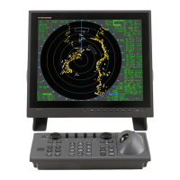
Mounting procedure
1. Fix the unit with four M6 bolts, or self-tapping screws.
25
340±1
380
385
410
350±1
2-φ7
FIXING HOLES
R3.5
370±1
7
2-FIXING NOTCH
#50
Floor mounting or bulkhead mounting
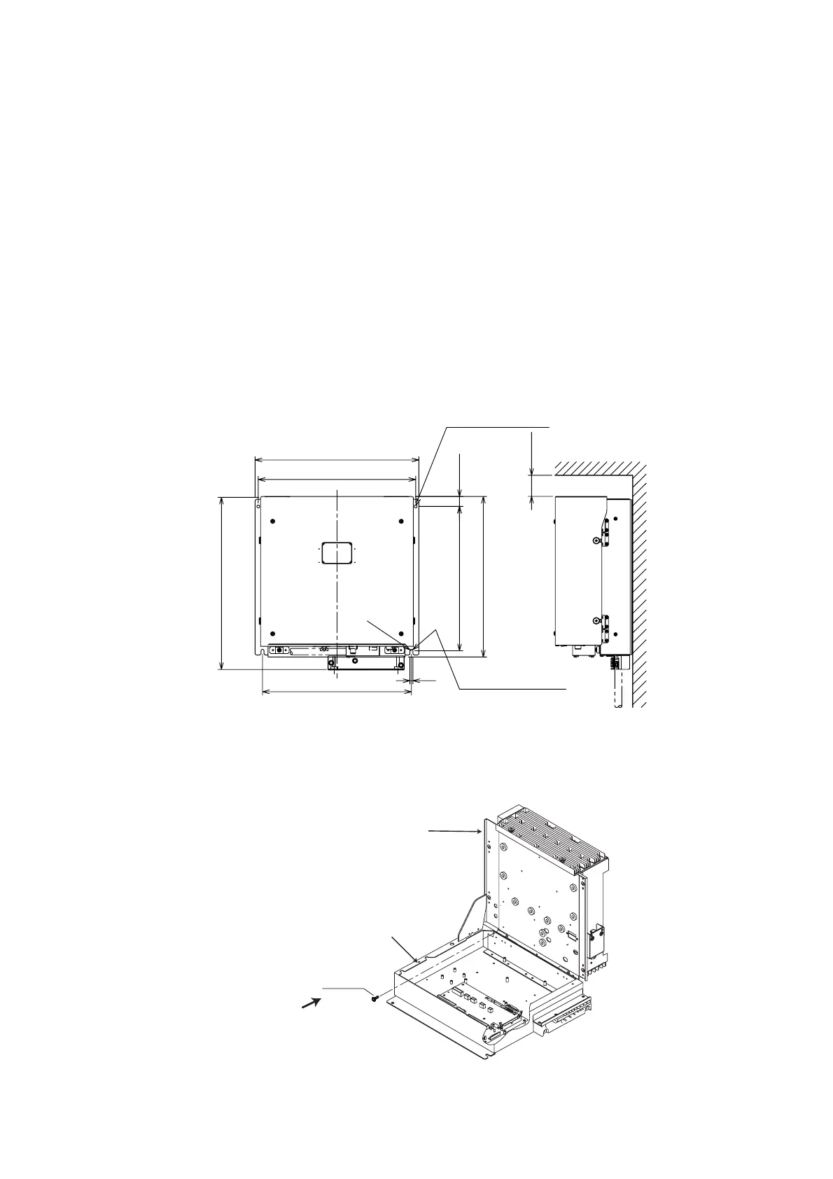
Note: If you fix the unit, cable entry upside, never remove the screw M3x10 that joints
the upper case assy. and lower case assy. of the processor unit.
Screw
M3x10
Upper case assy.
Lower case assy.
Never remove this screw.
Processor unit
 Loading...