Home
Furuno
Marine Radar
FAR-2117
Furuno FAR-2117 Service Manual
5
of 1
of 1 rating
563 pages
Give review
Manual
Specs
To Next Page
To Next Page
To Previous Page
To Previous Page
Loading...
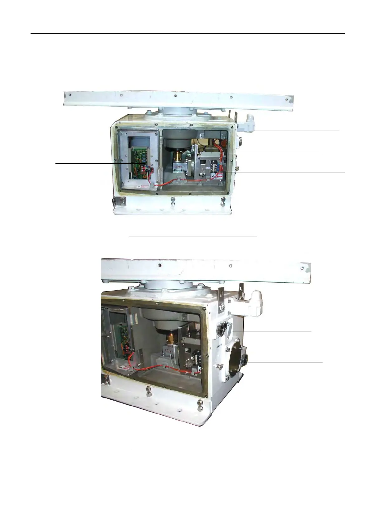
2.2 Scanner Unit
2-30
2.2.4 F
A
R-2827SW scanner unit
Fig. 2.
2.33 RSB-104 with Cover Removed
Fig. 2.
2.34 RSB-104 with Cover Removed
Antenna Switch
W
aveguide F
lange
MSS-7497 Board
TB for Antenna Motor Power Supply
Performance Monitor Antenna
Performance Monitor (PM-51)
145
147
Table of Contents
Table of Contents
77
Necessary Parts
13
Appendix 1) Sentences
87
Chapter 1. Configuration
93
Samples
94
Far-2827W
95
Inter-Switch
96
Configuration
97
Processor Unit: RPU-013
100
Cable
101
Extending Cables between Antenna Unit and Processor Unit
102
Antenna Unit
103
Applicable Model: FAR-2827W
104
Applicable Model: FAR-2137S, 2837S and 2137S-BB
105
Applicable Model: FAR-2837SW
107
Specifications
108
Monitor Unit
110
Current Power Consumption
111
List of Functions
112
Chapter 2. Location of Parts
117
Scanner Unit
127
FAR-2827W Scanner Unit
136
FAR-2837S Scanner Unit
140
FAR-2827SW Scanner Unit
146
Monitor Unit
150
Control Unit
153
Optional Unit
156
Radar Console
161
RCN-001/002: Slim Type
164
Chapter 3. Menu Tree
166
Arrangement of Icon Boxes
167
HDG/SPD/POS Display
169
Box Menu
170
Content
174
Speed]
175
Cursor]
176
Arp]
177
Ais]
178
Picture]
180
Brill]
182
Trail]
183
Mark]
184
Ant Information]
185
Main Menu Tree
186
Main Menu
193
Initialize Menu
200
Factory Menu
203
Chapter 4. System Setting
204
Overview of [FACTORY] Menu
205
Initialize Setting
216
Timing, Mbs, Ring Suppression
217
Default Ant Hieght, Near/MID/Far Stc Curve
218
Ant Revolution
220
Radar no
222
Radar
223
Inter -Switch
224
Main Operations for each Function
226
Model
227
Type: Imo/A/B/C/W
228
Pm Gain Adj
231
Turning on the Performance Monitor
232
Own Ship Info
233
Arp Preset
234
Network
237
Changing of IP Address
238
Jumper Setting of Terminal Board
242
Jumper of AIS Port: [J655]
243
Setting of Monitor Unit
244
Setting of AD-100 or GC-10
245
Setting List
247
Location of Parts
250
Addition to the Memory Card I/F: CU-200
251
Confirmation of IP Address
252
Selection of NAV DATA Input: [OS POSN]
253
Setting of [OS POSN] -> 3: SIO DATA LAN OUTPUT
254
Setting of RGB BUFF Board: 03P9229B
258
Output of RGB BUFF Board on FAR-2127
259
Setting of the Video Channel in the VDR
260
Alarm Output Setting
261
RCU-015 and 016
262
Setting of Alarm Output
264
Change of Power Input Type
267
Circuit Setting
268
Jumper Setting
269
Change of Antenna Speed: RSB-096 and RSB-097
270
Change and Adjustment of Antenna Speed
271
Change of Transmission HV Setting: HV-9017
272
Setup
273
Checking of Thermal Relay Setting
275
Thermal Relay of RTR-082
276
Sub Monitor
277
Change of the Connecting Ports
278
Slave Output Signal
279
Video Signals of S-Band Radar: Slave-1, 2 (J617, 618-#8Pin)
280
Examples of S-Band Radar Monitors
282
When Using as Slave Radar
284
Timing Adjustment
285
Connecting to the FEA-2X07
286
Chapter 5. Updating Program
287
Self Test
289
Connection of PC to Processor Unit (RPU-013)
290
Updating Program
292
Updating with a Card
295
Chapter 6. Maintenance
296
Self-Test
297
Description
298
Self-Test Screen-2
304
Factory Test
313
Contents
314
LED Check
318
Net-100
319
PWR Board
320
TX-HV Board
322
GC-10 Board
323
RF Unit
324
Control Unit
325
Error Messages
326
AIS ALARM Message
331
Replacement of Major Parts
332
Antenna Unit
333
Control Unit: RCU-014, RCU-015, RCU-016
334
Replacement of Boards Incorporated in RPU-013
335
PWR, HV and FIL Board
336
Replacement of Major Parts of TR Unit
337
References
338
Replacement of MIC
339
Saving to Card I/F Unit: CU-200
340
Battery Replacement of GC-10
343
Connection of EG-3000
344
Chapter 7. Block Description
345
Overall Block Diagram
346
Antenna Unit
349
Control between RFC Board and MD Board
350
MD Board (03P9244)
352
TX Trigger
353
Short Pulse and V TRIG Signal
354
RF Circuit
355
IF Board (03P9335)
357
B.P GEN Board (03P9347)
360
HD Signal
361
PWR (RF) Board (03P9348)
362
MSS Board (MSS7497)
365
Turning Operation
367
Manual Tuning
368
Automatic STC (SEA AUTO)
369
Processor Unit (RPU-013)
371
TB Board (03P9342)
372
Connector
374
SPU Board (03P9337)
376
IF-VIDEO MIX Signal Input
379
Structure of Screen
380
Signal Processing
381
Echo Trail Processing: [TRAIL] Menu
382
Wiper Processing (WIPER)
383
Zoom
385
Examples of Factory Setting for each "Picture"
395
Power Board
407
Block Description of AC Power Board (03P9339)
410
Block Description of DC Power Board (03P9338)
412
TX-HV Board (HV-9017)
413
NET-100 Board (03P9332)
414
Control Unit
415
Monitor Unit
417
Block Diagram of Monitor Unit
418
Mu-231Cr
419
List of Monitor Units
420
Chapter 8 . Q & a
421
How to Call up the INITIALIZE and FACTORY Menus
421
What Is the Maximum Cable Length Usable between each Unit See Page.1-9
422
How Many Units Can Connect for the Inter-Switch Function See Page.4-19, 4-21 and 4-23
423
See Page.4-74
424
Which Chart Card Is Read When 2 Chart Cards Are Inserted into CU-200?
425
See Page.4-64
426
See Page. 4-25
427
Is There a Priority Order for NAV-Data Connecting Ports on the TB Board See Page.6-11
428
ARPA Targets Are Quickly Lost See Page.4-8
429
What Can be Saved on a Memory Card
430
Is It Possible to Make the Setting of AIS Static Information and to Send AIS
432
Show the Symbol Marks of the AIS and ARPA
433
Proper Menu Setting Is Not Known. How Can the Setting be Reset to the Default
436
How to Adjust the Magnetron after Being Replaced
439
Equation of Wave Propagation
441
False Echoes
442
Appendix 1) Sentences
444
Talker Names List
447
ACK - Acknowledge Alarm
448
BWR - Bearing and Distance to Waypoint – Rhumb Line
449
DBS - Depth below Surface
450
GGA - Global Positioning System Fix Data
451
GLL - Geographic Position, Latitude/Longitude
452
MTW - Water Temperature
453
RMC - Recommended Minimum Specific GPS/TRANSIT Data
454
VBW - Dual Ground/Water Speed
455
VTG - Course over Ground and Ground Speed
456
WPL - Waypoint Location
457
VDM - UAIS VHF Data-Link Message
458
AAM - Waypoint Arrival Alarm
459
BBM - UAIS Broadcast Binary Message
460
RSD - Radar System Data
461
TTM - Tracked Target Message
462
AP1.3 Configuration of the Sentence from ARPA(FAR) to ECDIS(FEA.)
463
TTM - Target
464
RSD - Radar System Data
465
AP1.4 Configuration of the Sentence from ECDIS(FEA) to ARPA(FAR.)
466
DTM - Datum
467
DPT - Depth
468
PAESF - Fix Target Acquire/Cancel
469
PAESW - Waypoint List
470
Appendix 2) Specifications
471
Display Unit
472
Power Supply
473
Optional Equipment
474
Contents of Drawings
489
Other manuals for Furuno FAR-2117
Installation Manual
135 pages
Installation Instruction
148 pages
Specification Sheet
8 pages
5
Based on 1 rating
Ask a question
Give review
Questions and Answers:
Need help?
Do you have a question about the Furuno FAR-2117 and is the answer not in the manual?
Ask a question
Furuno FAR-2117 Specifications
General
Brand
Furuno
Model
FAR-2117
Category
Marine Radar
Language
English
Related product manuals
Furuno FAR-2157
20 pages
Furuno FAR-2107
327 pages
Furuno FAR-2127
563 pages
Furuno FAR-2137S
563 pages
Furuno FAR-2167DS
20 pages
Furuno FAR-2157-BB
20 pages
Furuno FAR-2107(-BB)
312 pages
Furuno FAR-2107 Series
52 pages
Furuno FAR-2827
563 pages
Furuno FAR-2238S
332 pages
Furuno FAR-2835S
80 pages
Furuno FAR-2328-NXT
332 pages

 Loading...