1.1 Overview
1-1
1.1 Overview
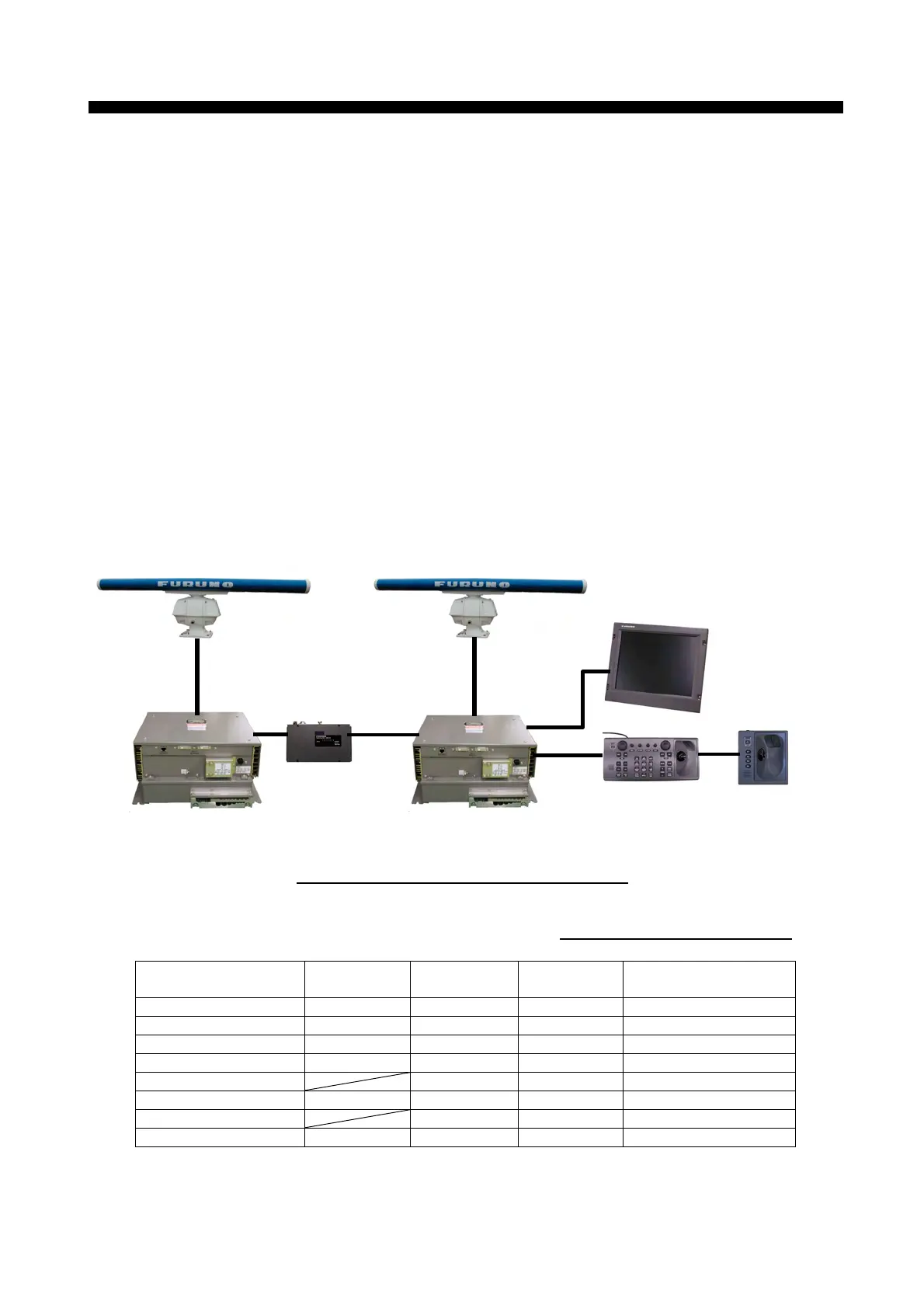
1) The system consists of a Processor unit, Monitor unit, Control unit and
Transceiver/Antenna unit. Communication between Transceiver/Antenna unit and
Processor unit, and Control unit by means of serial data (RS-422)
2) The ARPA and the Video plotter functions are incorporated in the SPU board as
standard.
3) The ARPA can acquire a maximum of 100 targets, and AIS can handle a maximum
of
1,000 targets.
4) The video signal for display complies with the DVI (Digital Visual Interface)
standard.
5) The system also has Inter-switch function using the LAN.
6) The antenna cable is a new type RW9600 (13C+2C2V), and the previous type
(24C+2C2V) is not compatible.
7) The I/O terminal block is assembled on the TB board in the Processor unit.
8) Other than the Antenna radiators are not compatible with existing radar systems.
Fig. 1.1.1 Example of System Configuration
Table 1.1.1 System Overview
Model Display Unit Band
Transmission
Output
Remarks
FAR-2137S 20.1 inch S-band 30 kW 2 unit type TR up
FAR-2837S 23.1 inch S-band 30 kW 2 unit type TR up
FAR-2837SW 23.1 inch S-band 30 kW 3 unit type TR down
FAR-2827W 23.1 inch X-band 25 kW 3 unit type TR down
FAR-2137S-BB S-band 30 kW 2 unit type TR up
FAR-2117/2127 20.1 inch X-band 12/25 kW 2 unit type TR up
FAR-2117/2127-BB X-band 12/25 kW 2 unit type TR up
FAR-2817/2827 23.1 inch X-band 12/25 kW 2 unit type TR up
LAN: 100 Base-T
HUB-100
(HUB)
RCU-014
(STD CONT unit)
MU-201CR (20.1 inch)
MU-231CR (23.1 inch)
(Monitor unit)
RCU-016
(Remote CONT unit)
RPU-013
(Processor unit)
RPU-013
(Processor unit)
Antenna unit
Antenna unit
Cha
ter 1. Confi
uration