6.3 LED Check
6-23
6.3 LED Check
6.3.1 Processor unit:
::
: RPU-013
1. SPU board
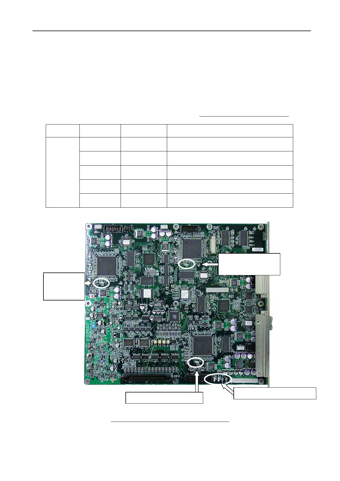
Table 6.3.1 LEDs on SPU board
Board Part number Normal status Function
CR2 Light
Check for Vcc: +5 VDC supply from PWR
board.
CR3 Light
Check for Vcc: +3.3 VDC supply from PWR
board.
CR4
Blink
every second
RUN check of Main CPU (U21)
CR5
Blink
every second
RUN check of DRW CPU (U19)
SPU
(03P9337)
CR8
Blink
every 0.5 second
RUN check of ARPA CPU (U74)
Fig. 6.3.1 Location of LEDs on SPU Board
DRW CPU
(U19)
ARPA CPU
(U74)
MAIN CPU
(U21)
CR8
(Blink
every
0.5 second
)
CR4
(Blink
every second
)
CR5 (Blink
every 1 second
)
CR2/CR3 (Normally light)

 Loading...