4.4
Initialize Setting
Initialize Setting Initialize Setting
Initialize Setting
4-30
4.4.11 OWN SHIP INFO
INITIALIZE -> 5
5 5
5
“2: LENGTH/WIDTH” data is used to draw the OWN SHIP MARK.
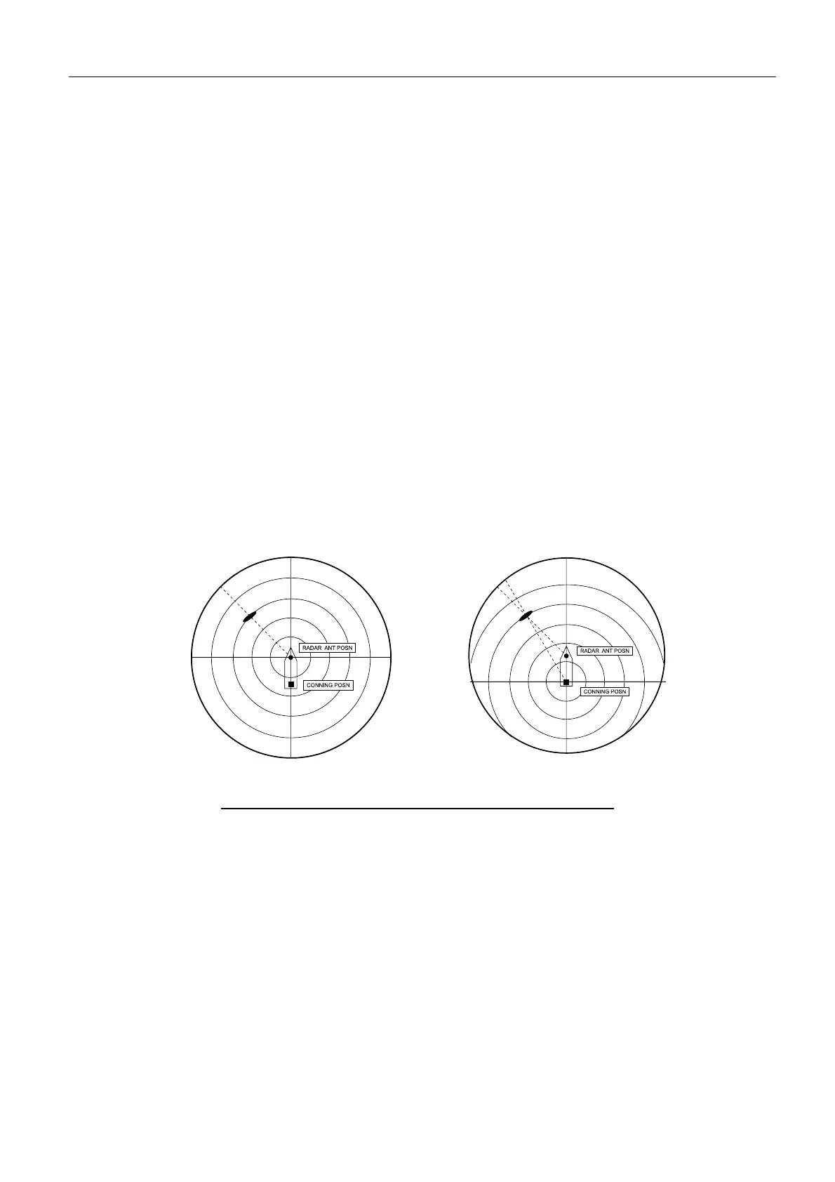
“3: SCANNER POSN” and “6: CONNING POSN” data determine the origin of a radar
graphic data. The figures below show the origin of range ring by the selection of [REF
POINT]. The graphic data, VRM, EBL, ARPA target, cursor and positioning of AIS
target mark are caluculated from the [REF POINT]. Selecting the “CONN POSN”,
those data coincides with the crew’s eye even if the scanner position is away from the
conning position.
“4, 5: GPS ANT POSN” data is used for L/L calculation of the cursor position on the
screen. The displayed position data in the [OS POSN] is the GPS antenna position.
Note:
“[INSTALLATION] -> 5: RADAR POSN” data is used for video signal processing of
echo trails and echo averages.
Fig. 4.4.11 SCANNER POSN and CONNING POSN View
CONNING POSN
SCANNER POSN

 Loading...