1.1 Overview
1-4
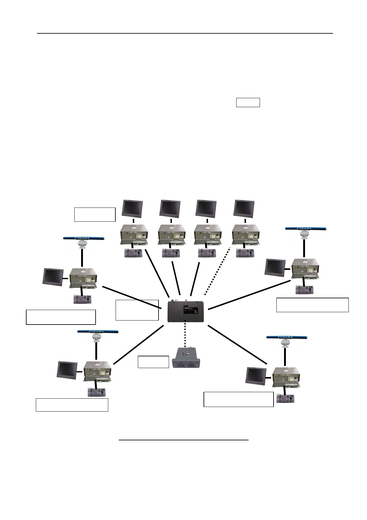
1.1.2 Inter-switch
For example, when Processor units are connected with the LAN via Hub, each
Processor unit can control the other Transceiver unit. Maximum eight Processor/Display
units can be controlled via Hub as Fig.1.1.6, and any of four Transceiver units are
selected from a Processor/Display unit by clicking the icon of ANT-X.
“X” means a radar number, for example, when switching the radar from No.1 to No.2,
operations for GAIN, STC, FTC and Range change are interlocked with each other and
can operate from either side. When connecting with the Card interface (CU-200), you
can read/write/share the data from respective Radars.
This Inter-switch function is executed by using the IP address associated with the Radar
number. Each Radar number can set on [Menu] -> 0 -> 4:RADAR NO., note that The
RADAR NO. 1 to 4 are Radars (with Antenna unit) and the No.5 to 6 are the monitors
(without Antenna unit).
Fig. 1.1.6 Example of Connection with LAN
HUB-100:
(8 port HUB)
CU-200
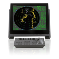
No.1 FAR-2xx7
series
No.4 FAR-2xx7
series
No.3 FAR-2xx7
series
No.2 FAR-2xx7
series
LAN: 100BASE-Tx
(Devices are identified by the
IP address.)
Monitor x 4

 Loading...