7.2 Antenna Unit
7-18
7.2.5 PWR (RF) board (03P9348)
The PWR (RF) board has different parts for X-band and S-band radars and is not
compatibly used for different band radars.
Table 7.2.3 Differences of PWR(RF) board
Difference
Name of
PWR(RF)
Applicable
radar type
JP21 R29
Heater V
(Short pulse)
Heater V
(Long pulse)
03P9348A
X band
6/12 kW
Open 2.2 k 7.5 V ----
03P9349B X band 25 kW Open 2.2 k 8.3 V 7.0 V
03P9350C S band 30 kW Short 3.3 k 9.5 V 7.7 V
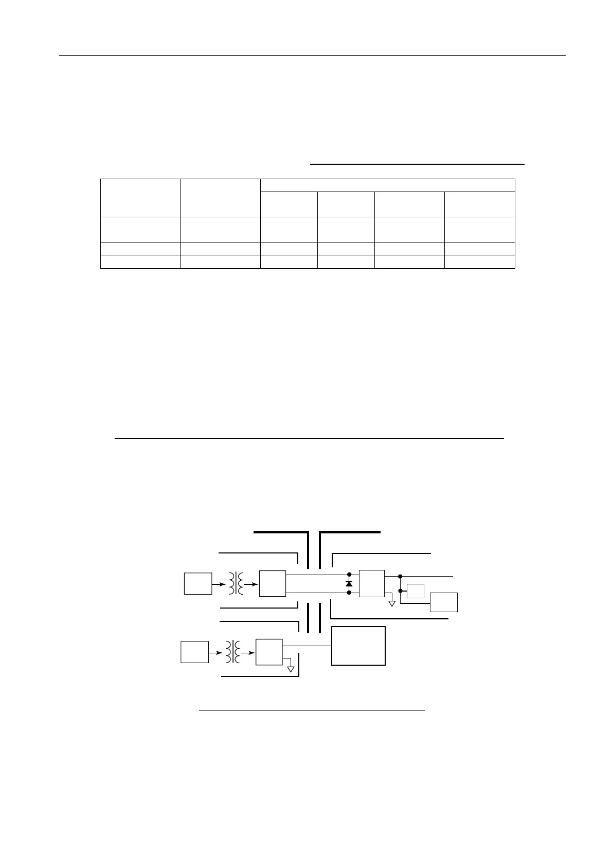
When supply voltages are supplied from the Processor unit, line voltages drop by the
antenna cable. It causes differences in potential on the ground between the Processor
unit and Antenna unit, thereby resulting in unstable voltage on the earth lines of cables.
For this reason, the power supply to the Antenna unit is featured as follows:
The power to the Antenna unit is supplied in +24 VDC alone except for the TX-HV and
motor line. Required voltage is generated in the Antenna unit based on this power
supply.
Connection of negative line for GND:
RPU-013 unit side TR unit side
For TR unit power supply: +24 VDC No Yes
For motor power supply:+24 VDC Yes No
(X-band radar)
For TX-HV power supply: 500V Yes No
Fig. 7.2.13 Earth Line of HV and +24 V Lines
SW REG.
REC
+5V
REG
-24V
+24V
(L1)
FILTER
Low
Voltage
Protect
CR2
(D4F60)
RPU-013
PWR p.c.b
SW REG.
REC
TX HV
HV p.c.b
RF PWR p.c.b
MD p.c.b
ANT unit

 Loading...