7.2 Antenna Unit
7-19
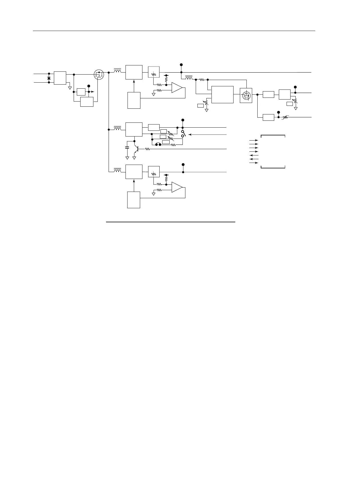
Fig. 7.2.14 Block Diagram of PWR (RF) board
- Low voltage protection circuit
+24V inputs from RPU-013 enter Q3 via the power supply filter circuit. The gate
of Q3 is controlled by signals of the low voltage protection circuit U2 and turns off
Q3 when the input voltage is reduced to +16.8 VDC or less. The starting voltage is
19.5 V or more.
- +12 V power supply circuit
U11 is the switching power supply of +12 VDC/1.7 A and operates at 60 kHz. Q11
and C13 connected to the SS terminals of U11 are circuits for output control and
soft start. The soft start function is provided to suppress the supply rush current of
the load. R13 to R16 and U12 are output overcurrent protection detection circuits
which controls the SS terminals of U11 when the current of 2.5 A to 3 A runs on
the +12 VDC line and stops the output of this line. The overcurrent protection
circuit is automatically reset.
- +32 V,
-
12 V power supply circuits
The +12 VDC power supply also outputs to the switching power supply U41. U41
operated at 33 kHz. This output generates voltages of +32 VDC/10 mA and –12
VDC/0.3 A. The voltage of +32 VDC is generated at U51:REG and adjusted to
+32 VDC at R62. The voltage of –12 VDC is adjusted so as to achieve –12 VDC at
R57. When the current of 0.55 A or more runs through the –12 VDC line, the RT41
(Poly Switch) is activated to shut off the output.
Q22
C23
U21
(SI 8015)
Q11,C13
-SOFT
START
VOLTAGE
CONTROL
VOLTAGE
CONTROL
U1
(AN78L05)
+5V
REG
-24V
+24V
(L1)
FILTER
U2(M519578FP)
Q1
+12V
+12V
HEATER H
HEATER V
HEATER OFF
TP4
U51
(uPC317HF)
TP3
PR5V
+32V
TP7
-12V
+5V
TP6
TP5
U12
Q3(2SJ265)
U11
(SI 8120)
VOLTAGE
CONTROL
U41
(MC34063AP1)
Low
Voltage
Protect
TP1
PR+5V
Serise
REG
Q41(2SJ256)
REC
REC
REC
REC
Q31,C33
VOLTAGE
CONTROL
PR5V
U22
U31
(SI 8010)
REC
L11,CR11,C14
CR52,C51
CR41,C45
L21CR21,C24
L31,CR31,C38
L3
L2
L4
L5
R47,47
R13-16
SS
SS
ss
R28
R32
JP21
R52,59
COMP
R57
R62
Vcc
IPk
SW
RT41
CR2
(D4F60)
60kHz
125kHz
250kHz
J833
1. -12V
2,7,9,12. GND
3. +5V
4,5. +12V
6. +32V
8. HEATER VLT
8. HEATER OFF
10. HEATER H
- Output
CONT
-SOFT
START
- Output
CONT

 Loading...