HCEN12630 Revision 07.2015
Program version 1.xx
AK 98™ Dialysis Machine - Technical description 79
3.3.3.6.3 Flow Calculation - UF Protective system
The UF Protective feature has two additional flow meters installed in the flow path, as
shown in Figure 3-9 “See chapter 11: "Fluid unit - flow path"” on page66. These
sensors measure the same physical flow as the UF control system, and provide
independent flow data for the UF protective system. The UF protective system is used
as supervision of the UF control: It is monitored with alarm limits and displayed.
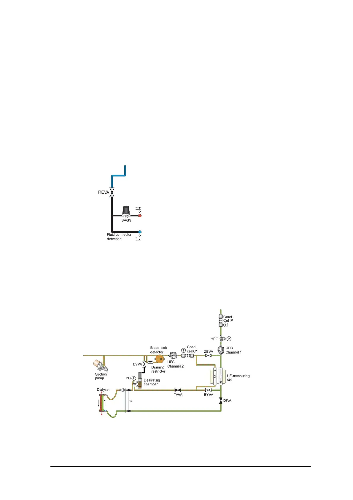
3.3.3.6.4 Safety Guard
When the machine is not in treatment mode the dialyzer tubes are placed in the safety
coupling, where the pressure is monitored by the SAGS – Safety Guard Switch. It
ensures that none of the hygiene programs can be started when the tubes are
removed from the coupling.
The function SAGS is doubled by mechanical switches which sense the presence of
the connectors.
Figure 3-19. See chapter 11: "Fluid unit - flow path".
3.3.3.6.5 Deaerating
In case of worn O-rings inside the dialyzer connectors (the Hansen connectors), an
incorrectly placed tube or insufficient priming of the dialyzer, the returning fluid will –
due to the negative pressure – contain air-bubbles which must be removed before it
reaches channel 2. This process takes place in the deaerating chamber:
Figure 3-20. See chapter 11: "Fluid unit - flow path".
The fluid level in the chamber is monitored by a ring-shaped floater, containing a
magnet which activates a reed relay if the level drops below approx. 15 mm. The
 Loading...