Home
Gambro
Medical Equipment
AK 98
Gambro AK 98 Service Manual
4
of 1
of 1 rating
276 pages
Give review
Manual
Specs
To Next Page
To Next Page
To Previous Page
To Previous Page
Loading...
HCEN12630
Revision
07.2015
Program
version
1.xx
AK
98™
Dialysis
Machine
-
T
echnical
description
91
3.4.2
T
reatment
modes
and
disposables
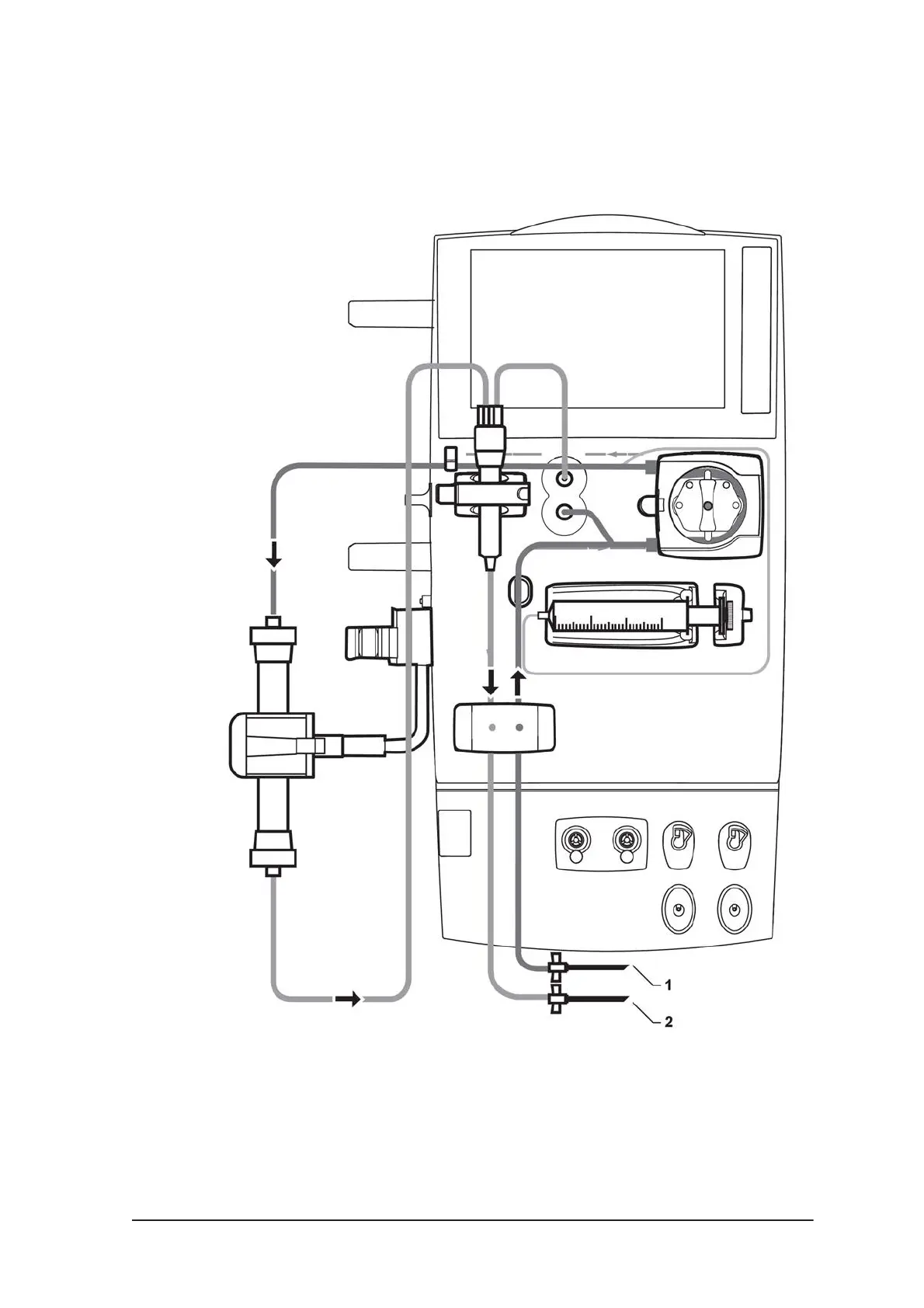
3.4.2.1
Double
needle
treatment
Figure
3-27.
Arterial
and
venous
blood
lines
setup
in
HD
-
double
needle
mode
1.
Arterial
blood
line
2.
V
enous
blood
line
92
94
Table of Contents
Section 1
3
Table of Contents
3
Section 2
8
1 General Information
13
About this Manual
14
Complaint
14
Installation
14
Safety Definitions
14
Competence of an Authorised Service Technician
15
Maintenance
15
Responsibility and Disclaimer
15
Connection of AK 98 Dialysis Machine to Other Electrical Equipment
16
Repair
16
Symbols
16
Technical Support
16
Waste Disposal
16
2 Ak 98™ Installation Guide
21
Before Installation
22
Installation Procedure
22
Manufacturer
22
Qualification Requirements
22
Record of Installation
22
Step 1 - Unpacking the Machine
22
Tools
22
Step 2 - Inspection of Delivered Equipment
23
Step 3 - Remove the Machine from the Pallet
23
Step 4 - Additional Package Box
24
Step 5 - Dialyzer Connector Set, Red
24
Step 6 - Dialyzer Connector Set, Blue
25
Step 7 - Transportation Handle
25
Step 8 - Pick-Up Tube Holder
26
Step 10 - Dialyzer Holder
27
Step 9 - Ultrafilter (Option)
27
Step 11 - Top Tray
28
Step 12 - BPM: Cuff Holder and Cuff (Option)
28
Step 13 - Infusion Stand
29
About RP 98
30
Prepare
30
Step 14 - Remote Panel, RP 98 (Option)
30
Installation Process - RP 98
31
Step 15 - Water Supply
34
Step 16 - Drain
35
Step 17 - Suction Tube for Chemical Intake
36
Step 18 - Potential Equalization Connector
36
Step 19 - Power Supply
37
Step 19 - Power Supply, Instructions for Home Installation
39
Step 20 - Placement of Warning Labels
40
Initial Start-Up Procedure
41
Presets for Chemical Disinfection with WRO Unit
42
Disinfection
43
Presets
43
Required Presets
43
Required Presets in WRO 300 /WRO 300 H
43
Requirements
43
Requirements and Presets for Performing Central Chemical
43
Requirements and Presets for Performing Integrated Heat Disinfection
43
WRO 300 H Communication
43
Communication Cables
44
Service Reporting - Dialysis Machine Installation
44
Supervision of the Disinfectant Conductivity
44
Installation Checklist
45
3 Technical Description
47
Blood Unit
49
Fluid Unit
49
General Information
49
Introduction
49
Operator's Panel
50
Power Supply
50
Blood Unit - Exterior Parts
52
Product Description
52
Blood Unit - Interior Parts
54
Fluid Unit - Exterior Front Parts
56
Fluid Unit - Exterior Rear Parts
58
Fluid Unit - Interior Parts 1
60
Fluid Unit - Interior Parts 2
62
Fluid Unit - Interior Parts 3
64
Fluid Unit - Valves
66
Fluid Unit Description
67
Subsystems
67
Fluid Unit - Flow Path
68
Fluid Unit - Flow Path Description
69
The Water Intake and Heating System
69
Description
70
The Temperature Control and Protective System
70
Disinfectant Inlet
72
Conductivity Control
73
Mixing
73
Composition Supervision
75
Conductivity Control System, Bicarbonate
75
Degassing Circuit
76
Degassing/Flow Pump System
76
Preset of the Degassing Pressure
77
Degassing Pressure Control System
78
Adjustable Dialysis Fluid Flow
79
Conductivity Guard
79
Fluid Output
80
Fluid Output - UF Control System
80
TMP Calculation
80
Deaerating
81
Flow Calculation - UF Protective System
81
Safety Guard
81
UF Control
82
The UF Control System
83
UF Control Taration
83
The UF Supervision System
85
3.3.3.6.10 UF Protective Taration
86
Diascan ® - Conductivity Cell C (Option)
87
3.3.3.6.12 Blood Leak Detection
88
FM Component Description
89
Extracorporeal Blood Circuit Description
92
Product Description - Blood Unit
92
Double Needle Treatment
93
Treatment Modes and Disposables
93
Single Needle Treatment
94
Blood Flow
95
Blood Flow Description
95
Blood Flow Diagram
95
BPM - Blood Pressure Module (Option)
97
BM Component Description
98
Single Needle Treatment
98
Power Supply
102
Operator's Panel
103
4 Technical Data and Specifications
105
Blood Flow Control
106
Heparin Pump
106
Performance and Specification - Control System
106
Priming
106
Blood Pressure
107
Blood Pressure Monitor (BPM)
107
Dialysis Fluid Preparation
108
Diascan™ (Option)
109
Profiling
109
Ultrafiltration Control
109
Ultrafiltration Protective
109
Disinfection and Cleaning - Chemical Disinfection
110
Disinfection and Cleaning - Heat Disinfection
110
Auto Heat Disinfection
111
Disinfection and Cleaning - Rinse/Drain
111
Heat Disinfection Program Including WRO 300 H
111
Disinfection and Cleaning - Exterior Cleaning
112
Water Supply
112
Connection of External Equipment
113
Power Supply
113
Battery Back-Up
114
Blood Pressure Supervision
114
Performance and Specification - Supervisory System
114
Air Detection
115
Blood Leakage Detection
115
Dialysis Fluid Preparation
115
Extracorporeal Blood Loss Due to Coagulation
115
Tmp
115
Alarm Sound Pressure
116
Dimensions and Weight
116
Infusion Stand
116
Materials in Contact with Dialysis Fluid, Concentrates, and Water
116
Metals
116
Physical Data
116
Polymers
116
Electromagnetic Environment
117
Environmental Data
117
Operation
117
Other Materials
117
Transportation and Storage
117
Energy Consumption
120
Expected Service Life
120
Standards
121
5 Maintenance Support
123
About the Service Menu
125
Access the Service Menu
125
Enter Service or Preset Mode
125
Service Menu
125
Error List
126
Installed Features
126
Logging
126
Machine
126
Main Mode
126
Main Mode Overwiew
126
Fluid Unit
127
Logging
127
Preset Mode
128
Preset Mode Overview
128
Presets
128
To Display Logging Parameters
128
Preset Parameter List
129
Presets Variables
129
Main Preset Group
130
Manual Preset
130
To Do a Manual Preset
130
Export and Import Presets
131
Language
131
To Export Presets
131
To Import Presets
131
Default Preset
132
Service Mode
132
Service Mode Overview
132
To Configure Multiple Dialysis Machines
132
To Edit Preset Files Offline
132
Calibration
133
Calibration Menu
133
Chemical Status
133
To Abort the Chemical Disinfection Program
133
Utility
133
Utility Tasks
133
When to Abort Chemical Disinfection
133
Sensor Tests
134
Service Test Types
134
Service Tests
134
To Do a Service Test
134
About Diagnose
135
Diagnose
135
Fluid Path Leakage Test
135
Pump Test
135
Service Drain
135
System
135
System Tasks
135
Error Codes
136
To Scan Transducers Via the Data Bus
136
To View Technical Errors
136
Blood Module
137
Blood Module Tasks
137
To Erase Technical Errors
137
To Start BPM Tests
137
Air Leakage Test
138
BPM Sub-Tests
138
Check of Air Leakage
138
Check of Inflation Speed
139
Check of Pressure Transducer
139
Inflation Test
139
Pressure Test
139
5.4.4.3.10 Check of Pressure Transducer Calibration and Measured Pressure
140
5.4.4.3.12 to Start a Pump Test
140
To Start Lamps Test
140
Fluid Module
141
Fluid Module Tasks
141
Variable Flow
141
Fluid Module Pumps
142
UF Sensor Values
142
To Perform a UF Taration
143
Update AK 98™ System Firmware
143
Valves
143
Replacements
145
Actions after Component Replacement
146
Replacement Matrix
146
Actions to be Done - Description
148
Fluid Unit - Flow Path
150
Battery
151
Battery and Electronic Waste Handling
151
Replacement of Batteries
151
7 Calibrations
153
Compensation Values
155
General Information about the Calibrations
155
The Data Bus
155
Installation of New Pressure Tranducers
157
Calibrations
158
I2C Data Bus Errors
158
Why Is Calibration Needed
158
Calibration Errors
159
Calibration Errors - Pressure Transducers
159
Calibration of Linear Transducers
160
Linear Transducers
160
Test Equipment
160
Venous Pressure Transducer Calibration
161
Arterial Pressure Transducer Calibration
162
Blood Pump
164
Occlusion Adjustment
164
Priming Detector Calibration
164
Adjustment Instruction
165
Blood Leakage Detector Calibration
165
Blood Pump
165
Variable Flow Calibration
166
About Conductivity Transducer Calibration
167
Conductivity Transducer Calibration
167
To Calibrate Conductivity Transducer
167
Dialysis Pressure Transducer Calibration
168
Degassing Pressure Transducer Calibration
170
HPG Pressure Transducer Calibration
171
Pressure Regulator Calibration, PR 1
173
Pressure Regulator Calibration, PR 2
174
General
175
UF Control Calibration
175
UF-Measuring Cell and Calibration Modes
175
Prerequisite for the Complete UF Control Calibration
176
Complete Mode
177
During the UF Control Calibration
177
UF Control Calibration in Complete Mode
177
When the Automatic UF Control Calibration Is Finished
178
If the Calibration Is out of Limits
179
Internal Mode
179
To Disconnect the UF Calibration Box
179
UF Control Calibration in Internal Mode
179
During the Verification of the UF Control Calibration
180
UF Control Calibration in Verify Mode
180
Verify Mode
180
When the Verification of the UF Control Calibration Is Finished
181
8 Maintenance Manual
183
General
184
Preventive Maintenance Procedures
184
How to Open the Machine
185
How to Remove the Rear Cover
185
Opening Illustration
185
How to Remove the Blood Monitor (BM)
186
Test Equipment
186
Water Inlet Tube Disinfection
186
Parts in the Base-Kit
189
Preventive Maintenance: Base-Kit
189
How to Exchange the Parts Included in the Base-Kit
190
Actions to Carry out after the Parts in the Base-Kit Have Been Exchanged
194
Parts in the A-Kit
203
Preventive Maintenance: A-Kit
203
How to Exchange the Exterior Parts Included in the A-Kit
204
Actions to Carry out after the Parts in the A-Kit Have Been Exchanged
206
Parts in the B- and C-Kit
207
Preventive Maintenance: B- and C-Kit
207
How to Exchange the Parts Included in the B- and C-Kit
208
Replacing Valve Membranes
210
Valve Membranes
210
Valve Mounting Tool K15391C
210
Actions to Carry out after the Parts in the B- and C-Kit Have Been Exchanged
211
9 Electrical Safety Inspection
213
General
214
For AK 98
215
PET - Protective Earth Test
215
PET Prerequisites
215
Test Equipment for PET
215
Visual Inspection
215
Earth Leakage Current Test
216
Elt
216
Elt/Plt
216
General Conditions for ELT / PLT
216
Test Equipment for ELT / PLT
216
Limit Values for Earth Leakage Current (ELT)
217
Patient Leakage Current Test
217
Plt
217
Limit Values for Patient Leakage Current (PLT)
218
Machine Type and Identification
218
Record of Electrical Safety Inspection
218
ELT - Earth Leakage Current Test
219
PET for AK 98™ Dialysis Machine
219
PLT - Patient Leakage Current Test
219
12 Functional Check
229
About Functional Check
231
Definition
231
Functional Check
231
The Difference between Basic Functional Check and Extended Functional Check
231
The Different Parts in Functional Check
231
Operation During Functional Check
232
Purpose with this Chapter
232
POST - Power on Self Test
233
Test Philosophy
236
Functional Check Overview
237
Common Tests
238
Sub-Tests
238
Common Tests / Light Indicator Test
239
Common Tests / Safety Relay Test
239
Test Description
239
Test Objective
239
Common Tests / Valve Current Test - Communication Test
240
Common Tests / Valves Current Test
240
Safety Relay Test Description
240
Test Objective
240
Common Tests / Valve Current Test - CHVA
241
Common Tests / Valve Current Test - Close Failure Test
241
Common Tests / Valve Current Test - DIVA
241
Common Tests / Valve Current Test - BYVA
242
Common Tests / Valve Current Test - EVVA / TAVA
243
Common Tests / Valve Current Test - FLVA / DRVA / AIVA / FIVA / CBVA / HBVA
243
Common Tests / Speakers Test
244
Blood Monitor - Functional Check
245
Common Tests / Battery Test
245
Sub-Tests
245
Blood Pressure Transducer Test
246
Pressure Measurement
246
Zero Pressure Test
246
Negative Pressure Test
247
Positive Pressure Test
247
Relay Test
247
Priming Detector Test
248
Blood Pump Test
249
Arterial Clamp Test
251
Venous Clamp Test
251
Air Detector Test
252
Fluid Monitor - Functional Check
253
Sub-Tests
253
Flow Switch and Heater Relay Test
254
Overview
256
Valves Leakage Test
256
Fluid Path - Leakage Test
264
High Temperature Test
265
Temperature Test
265
Test Objective
265
Blood Leak Detector Test
266
Conductivity Test
266
Low Temperature Test
266
Sub-Tests
266
Low Conductivity Test
267
High Conductivity Test
268
Degassing Pressure Test
269
Test Objectives and Conditions
269
Test Description
270
AIVA Test
271
DIVA/TAVA/EVVA Closing Test
272
Overview
273
UF Supervision Taration Phase
273
UF Supervision Test
273
UF Supervision Evaluation Phase 1
274
UF Supervision Evaluation Phase 2
274
UF Supervision Function Check Time out
274
Automatic Restart of the FM Functional Check
275
Blood Leak Clean Test
275
Other manuals for Gambro AK 98
Operator's Manual
386 pages
4
Based on 1 rating
Ask a question
Give review
Questions and Answers:
Need help?
Do you have a question about the Gambro AK 98 and is the answer not in the manual?
Ask a question
Gambro AK 98 Specifications
General
Brand
Gambro
Model
AK 98
Category
Medical Equipment
Language
English
Related product manuals
Gambro AK 96
509 pages
Gambro Prismaflo IIS
2 pages
 Loading...