HCEN12630 Revision 07.2015
Program version 1.xx
AK 98™ Dialysis Machine - Technical description 87
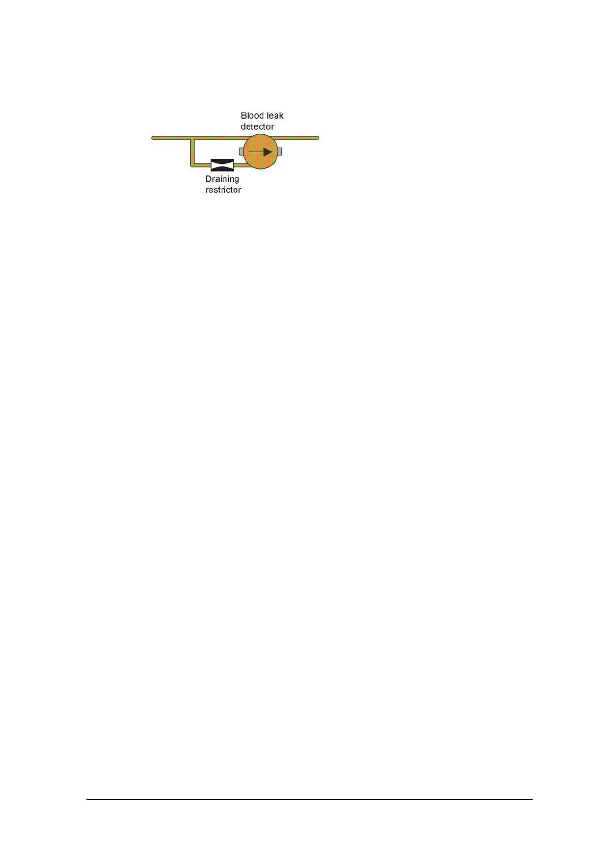
Figure 3-25. See chapter 11: "Fluid unit - flow path".
The restrictor in the bottom facilitates the complete draining and filling of the detector
house, by restricting the outflow, thus forcing the house to empty slowly and fill up
completely.
Finally, the dialysis fluid is led to the drain, via the suction pump, the outlet restrictor
and the heat exchanger.
3.3.4 FM component description
Pressure regulator, PR 1 & PR 2
Two different pressure regulators, with different springs inside, are used to decrease
the pressure in two steps.
PR1: 0.8 Bar/600 mmHg
PR2: 130 mmHg
Heat exchanger
The heat exchanger is used to raise the temperature on the inlet water. Machines
made for 230 V are equipped with two heat exchangers while machines made for 115
V are equipped with four heat exchangers.
Pressure switch: SAGS & INPS
The pressure switch is used to monitor if there is an inlet pressure (INPS) and if the dia
connectors are connected to the machine before a disinfection program is started
(SAGS).
The pressure switch is switching on and off as below:
SAGS: on = -74 mmHg off = -59 mmHg
INPS: on = 150 mmHg off = 99 mmHg
Flow Switch
The flow switch is used to check if there is flow through the heater. The flow switch
contains a glass tube, a floater, and an infrared sensor.
Heater unit
There are two different heater units:
● one for 115 V/1300 W
● one for 230 V/3*580 W.
The Heater unit for 230 V contains three windings of each 580 W. The heater unit is
controlled with a duty cycle.
 Loading...