GFC 600 AFCS Part 23 AML STC Maintenance Manual Page 20
190-01938-00 Revision 13
4.7 GSM 86 Slip Clutch Torque Check
Perform the test per Section 4.7.1 (preferred) or 4.7.2. To perform the procedure, all GFC 600
system equipment must be installed and operational.
4.7.1 Automatic Slip Clutch Torque Check
The GSM 86 servo gear box does not have an adjustable slip clutch; however, the torque value
can be measured using this procedure.
IMPORTANT!
It is highly recommended that the following test be performed at
temperatures between 50° F and 120° F.
1. Ensure that the aircraft is on the ground (weight on wheels).
2. Apply power to the aircraft avionics bus.
3. Ensure that power is not applied to the GMC 605 by pulling the AUTOPILOT circuit
breaker.
4. Start the GFC 600 in Configuration Mode by pressing and holding the FD button while
closing the AUTOPILOT circuit breaker. Release the FD button when the splash screen
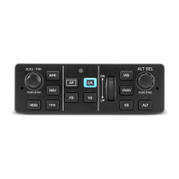
is displayed. Press the HDG button when CONT is displayed on the GMC 605.
5. Using the IAS and VS buttons and the UP/DN thumbwheel, navigate to the GFC Page
group.
6. Using the IAS and VS buttons and the UP/DN thumbwheel, navigate to the SERVOS
page in the GFC group.
7. Using the IAS and VS buttons and the UP/DN thumbwheel, select the PITCH, ROLL,
PITCH TRIM, or YAW axis, as required.
8. Using the IAS and VS buttons and the UP/DN thumbwheel, select the TST page.
9. Using the IAS and VS buttons on the UP/DN thumbwheel, select TEST THIS SVO, then
press the VS button to start the test process. NOTE: The flight controls in the selected
axis will move during this process.
10. After the test process is complete, the results are indicated by the color of the LEDs to
the left of the AP, FD, and YD buttons. Green LEDs indicate that the test passed. Red
LEDs indicate that the test failed.
11. Following directions on the GMC 605, firmly grasp the flight controls and press the AP
DISC/TRIM INT switch.
12. Using the UP/DN thumbwheel, select the CTL page, then select EXIT TEST, then press
the VS button.
13. Repeat steps 7 through 13 for each axis as required.
14. If the test fails in a specific axis (indicated by red LEDs to the left of the AP, FD, and YD
buttons), it is acceptable to repeat the test one time. If it fails a second time, perform the
procedures in Section 4.7.2 for the affected axis.
15. Remove power from the aircraft.
 Loading...