GFC 600 AFCS Part 23 AML STC Maintenance Manual Page 31
190-01938-00 Revision 13
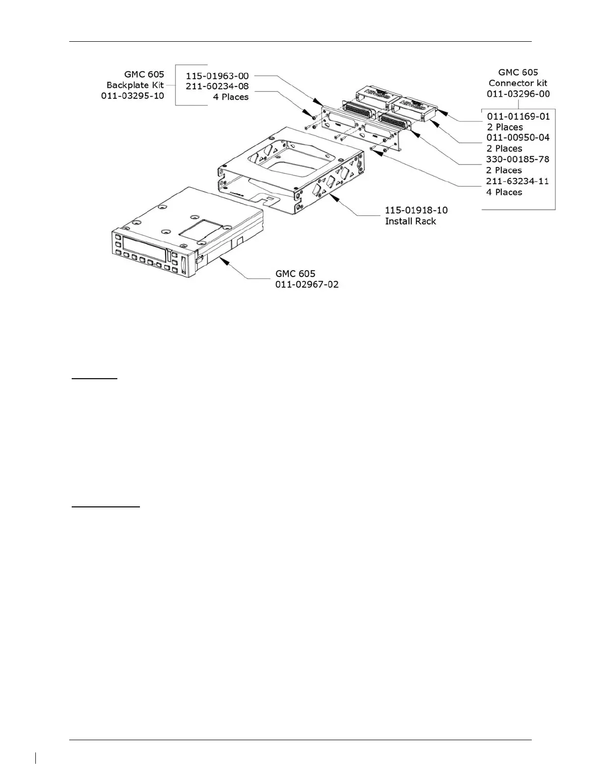
Figure 6-1 – GMC 605 Installation and rack/backplate assembly
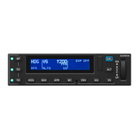
6.2 GI 285
Removal:
1. De-energize the GFC 600 system by pulling the AUTOPILOT Circuit breaker.
2. Insert a 3/32” hex drive tool into the access hole at the bottom of the face of the unit.
3. Turn the hex drive tool counterclockwise until the hex drive tool stops.
4. Pull the unit from the rack.
5. Detach P2851 from the mating connector on the GI 285.
Reinstallation:
NOTE:
Ensure the position of the GI 285 retention mechanism is correct by inserting a 3/32” hex drive
tool into the access hole at the bottom of the face of the unit and turning the tool counterclockwise
until it fully stops.
1. Visually inspect the connectors to ensure there are no bent or damaged pins. Repair
any damage.
2. Reattach P2851 to the mating connector on the GI 285.
3. Slide unit into the rack until it stops.
4. Insert a 3/32” hex drive tool into the access hole at the bottom of the face of the unit.
5. Push on the left side of the GI 285 bezel while turning the hex drive tool clockwise until
the unit is securely seated in the rack. Do not exceed 8 in-lbs of torque.
6. Perform a functional check of the GI 285 per Section 7.3.
 Loading...