GFC 600 AFCS Part 23 AML STC Maintenance Manual Page 35
190-01938-00 Revision 13
6.5 Air Data Module (ADM)
Removal:
1. Verify that the GFC 600 is de-energized by pulling the AUTOPILOT circuit breaker.
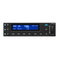
2. Remove the GMC 605 per Section 6.1.
3. Disconnect the pitot and static hoses from the ADM (not required when the ADM is used
as a cabin pressure sensor).
4. Detach the ADM wiring harness from the mating connector on the ADM by depressing
the lock tab and pulling on the connector.
5. Loosen the two attaching screws (in the GMC 605 rack) and slide the ADM to disengage
from the key slot holes in the rack.
Reinstallation:
1. Insert the two screws partially into the ADM.
2. Engage the ADM mounting screws in the key slot holes.
3. Slide the ADM to fully engage the key slots. Note that the ADM screws must be installed
through both the rack and the backplate assembly.
4. Tighten the mounting screws.
5. Connect the ADM wiring harness by lining up the connector and inserting it until the lock
tab engages.
6. Connect the pitot and static hoses to the appropriate ports on the ADM (not required
when the ADM is used as a cabin pressure sensor).
7. Reinstall the GMC 605 per Section 6.1.
8. Perform a functional check of the ADM per Section 7.6.
9. Perform a functional check of the GMC 605 per Section 7.1.
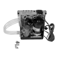
Figure 6-5 – ADM Installation
 Loading...
