GFC 600 AFCS Part 23 AML STC Maintenance Manual Page 30
190-01938-00 Revision 13
6. Equipment Removal & Installation
This section describes how to remove and replace equipment associated with this STC. After
removal and replacement, the system must be configured and tested as described in Section
6.7. Refer to the model-specific Installation Manual Addendums for unit locations and details.
Refer to the Master Drawing List, 005-01009-01 for the applicable addendum part number.
CAUTION:
When removing and/or replacing any GFC 600 component, always ensure
that aircraft power is off. Unplug any auxiliary power supplies.
NOTE:
MS21044-XX self-locking nuts are for one time use only and must be replaced if removed.
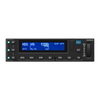
6.1 GMC 605
Removal:
1. De-energize the GFC 600 system by pulling the AUTOPILOT circuit breaker.
2. Insert a 3/32” hex drive tool into the access hole at the bottom of the face of the unit.
3. Turn the hex drive tool counterclockwise until the tool stops.
4. Pull the unit from the rack.
Reinstallation:
NOTE:
Ensure the position of the GMC 605 retention mechanism is correct by inserting a 3/32” hex drive
tool into the access hole at the bottom of the face of the unit and turning the tool counterclockwise
until it fully stops.
1. Visually inspect the connector and pins for signs of damage. Repair any damage.
2. Slide the unit into the rack until it stops.
3. Insert a 3/32” hex drive tool into the access hole at the bottom of the face of the unit.
4. Gently push on the GMC 605 bezel while turning the tool clockwise until the unit is
securely seated in the rack. Do not exceed 8 in-lbs. of torque.
5. Perform a software load (if required) and functional check of the GMC 605 as required
per Section 7.1.
 Loading...