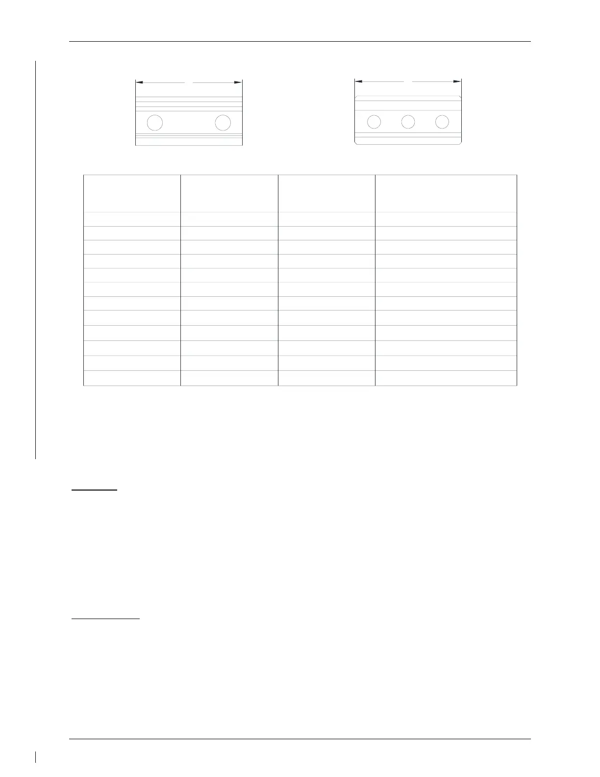
Bridle Cable Clamp
Main Cable Dia.
Length, L
Features
117-00164-04 .188" 1.250" 2 hole
117-01834-00 .063" 1.250" 2 hole, countersunk
117-00929-00 .063" 1.250" 2 hole
117-00930-00 .125" 1.375" 2 hole
117-00931-00 .156" 1.500" 2 hole
117-01381-00 .125" 2.000" 3 hole, countersunk
117-01412-00 .125" 2.000" 3 hole
117-01650-00 .125" 1.38"
3 hole, isolated
117-01650-01 .125" 1.38"
3 hole, countersunk, isolated
117-02030-00 .063" 1.250" 3 hole
117-02030-01 .125" 1.375"
3 hole, blue color
117-02030-02 .156" 1.500"
3 hole, black color
L
L
Bridle Cable Clamp (2 hole)
Bridle Cable Clamp (3 hole)
Figure 6-4 – Servo Cable Clamp Identification
6.4 GTA 82 Trim Adapter
Removal:
1. Ensure that there is no electrical power to the GTA 82 Trim Adapter by pulling the
AUTOPILOT circuit breaker.
2. Disconnect the electrical connector from the mating connector on the trim adapter
(P821).
3. Remove the GTA 82 using the data provided in the appropriate model-specific
installation manual addendum. Refer to the Master Drawing List 005-01009-01.
Reinstallation:
1. Visually inspect the connector to ensure there are no bent or damaged pins. Repair any
damage.
2. Reinstall the GTA 82 using the data provided in the appropriate model-specific
installation manual addendum. Refer to the Master Drawing List 005-01009-01.
3. Reconnect the electrical connector P821 to the mating connector on the GTA 82.
4. Perform a functional check of the GTA 82 per Section 7.4.

 Loading...