49 • Installation
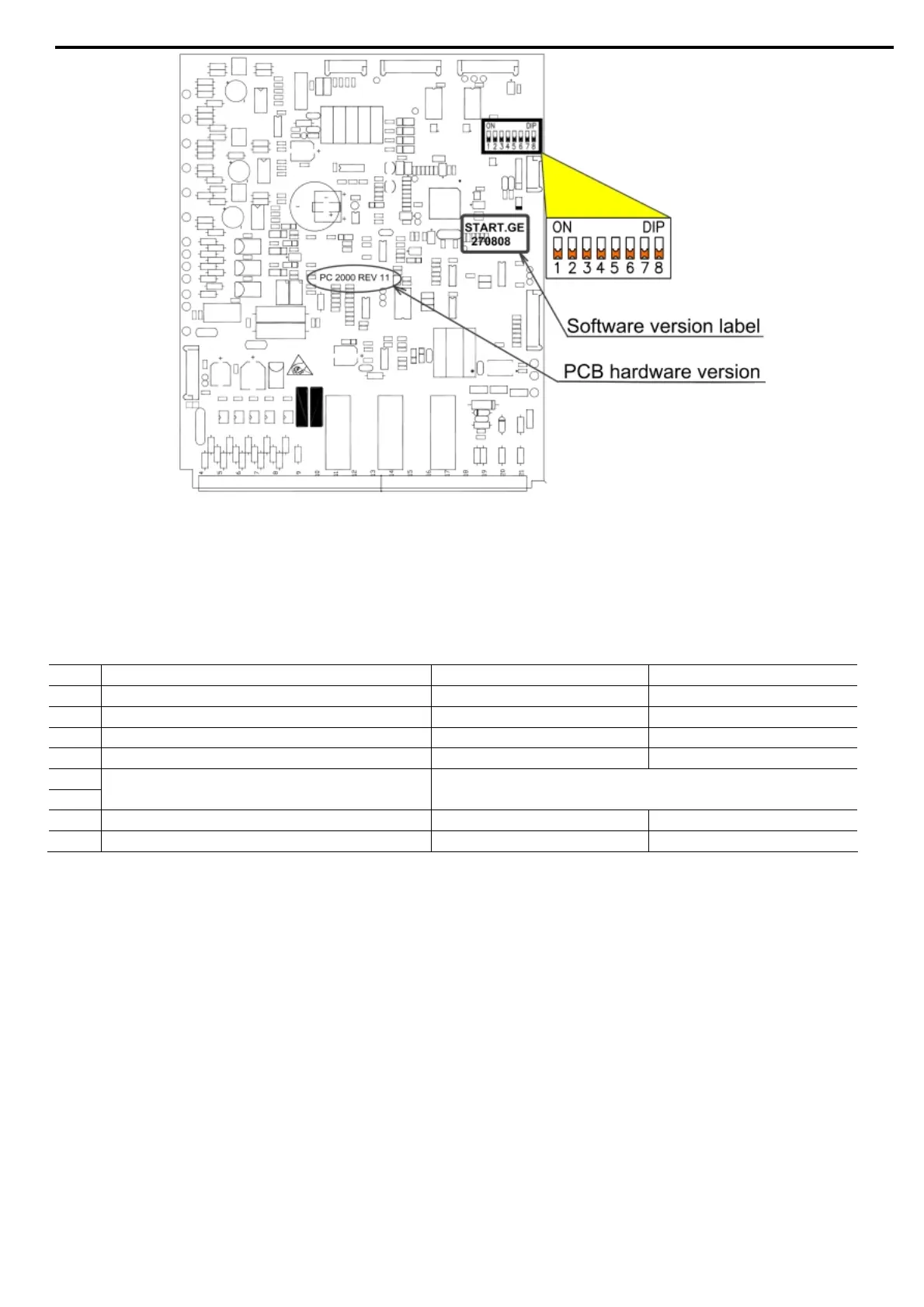
ASTAT-XT main PCB.
Dip switches location, software version label location and PCB hardware version identification.
5.5 Dip Switch Settings on the Main PCB
The dip
switch has eight separate switches. It is located under the front cover of the control module (models
QTx0085x-QTx1400) or under the display unit (models QTx0008x-QTx0072).
No. Switch Function Switch Off Switch On
1 Display format Minimized Maximized
2 Not Used - -
3 Mains/generator Mains Generator
4 Must be OFF - -
5 LCD language selection See tables below section 5.5.4 page 50.
6
7 Expanded settings Disabled Enabled
8 Software lock Open Locked
5.5.1 Switch # 1 – Display Modes
Two disp
lay modes are available:
Maximized – display of all possible parameters.
Minimized – display of pre-selected parameters.
Setting switch # 1 to OFF will minimize the LCD displays.
Refer also to section
4.6 page 23.
Maximized Mode - Switch #1 – On Minimized Mode Switch #1 – Off
Display Only
Main Settings
Start Settings
Stop Settings
Dual Settings
Slow SP & Saving Parameters
Fault Settings
I/O Settings Parameters
COMM. Parameters
Statistical Data
Display Only
Main Settings
Start Settings
Stop Settings
Statistical Data

 Loading...


