13 • Technical Specifications
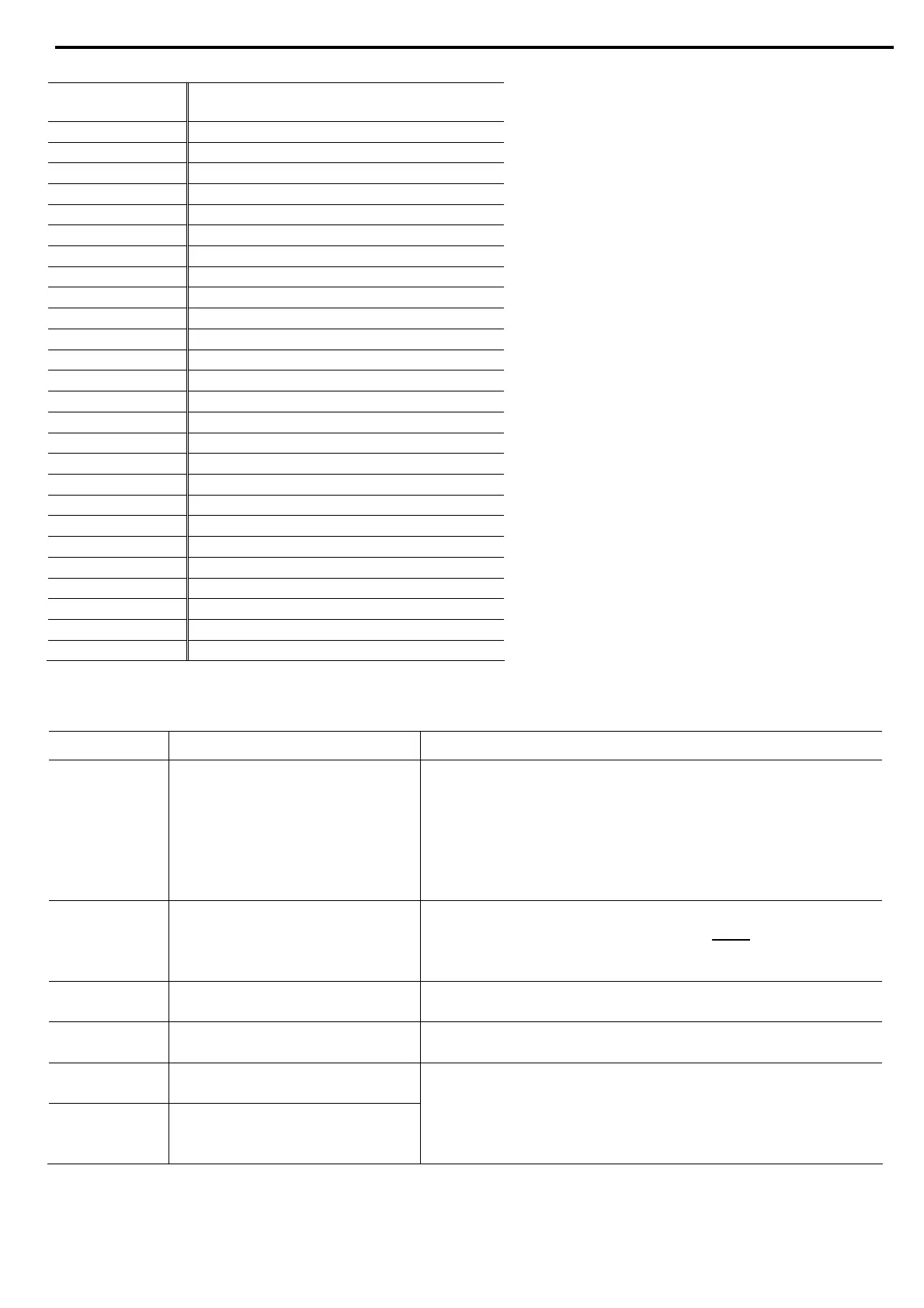
3.2 Weight
Model Weight
Kg Lbs
QTx0008Uxxxx 4.2 9.3
QTx0017Uxxxx 4.2 9.3
QTx0031Uxxxx 5.3 11.7
QTx0044Uxxxx 6.7 14.8
QTx0058Uxxxx 6.7 14.8
QTx0072Uxxxx 6.7 14.8
QTx0085Uxxxx 15.2 33.5
QTx0105Uxxxx 15.2 33.5
QTx0145Uxxxx 15.2 33.5
QTx0170Uxxxx 15.2 33.5
QTx0210Nxxxx 32.7 72.1
QTx0210Uxxxx 46.5 102.5
QTx0310Nxxxx 32.7 72.1
QTx0310Uxxxx 46.5 102.5
QTx0390Nxxxx 32.7 72.1
QTx0390Uxxxx 46.5 102.5
QTx0460Nxxxx 58.4 128.7
QTx0460Uxxxx 61.8 136.2
QTx0580Nxxxx 63.2 139.3
QTx0580Uxxxx 69.5 153.2
QTx0650Nxxxx 64.8 142.9
QTx0820Uxxxx 69.5 153.2
QTx0950Nxxxx 86.7 191.1
QTx1100Nxxxx 169.8 374.3
QTx1400Nxxxx 175.5 386.9
3.3 I/O Terminal Board Specifications
Refer to dra
wing on page 17.
Terminal Function Description
1L1, 3L2, 5L3 Connection to mains voltage up
to 690V
Thyristor’s PIV rating, internal circuitry and insulation defines
three voltage levels:
QT 1 x : for 230-500V +10%/ -15% 50/60Hz
QT 2 x: for 460-600V +10% /-15% 50/60Hz
QT 3 x: for 690V +10% /-15% 50/60Hz
Each ASTAT-XT is suitable for one of the above levels & for
50/60 Hz.
A, B, C Preparation for bypass
connection
Bypass preparation is standard in all models.
All models from ASTAT-XT 950A and up must
be operated
with a bypass contactor.
Refer to section
5.3 page 47 for more details.
2T1, 4T2, 6T3 Connection to motor
Connect motor’s terminals to these terminals/busbars.
G Connection to ground For proper operation and for safety reasons soft ASTAT-XT
must be properly grounded.
Terminal L Control phase The control voltage operates the electronic circuitry and the
fans (when they exist).
Terminal N Control neutral (return) Two control voltages are available:
QT x xxxx x 1 x x S for 110V +10%/-15% 50/60Hz
QT x xxxx x 2 x x S for 230V +10%/-15% 50/60Hz

 Loading...


