67 • Application diagrams
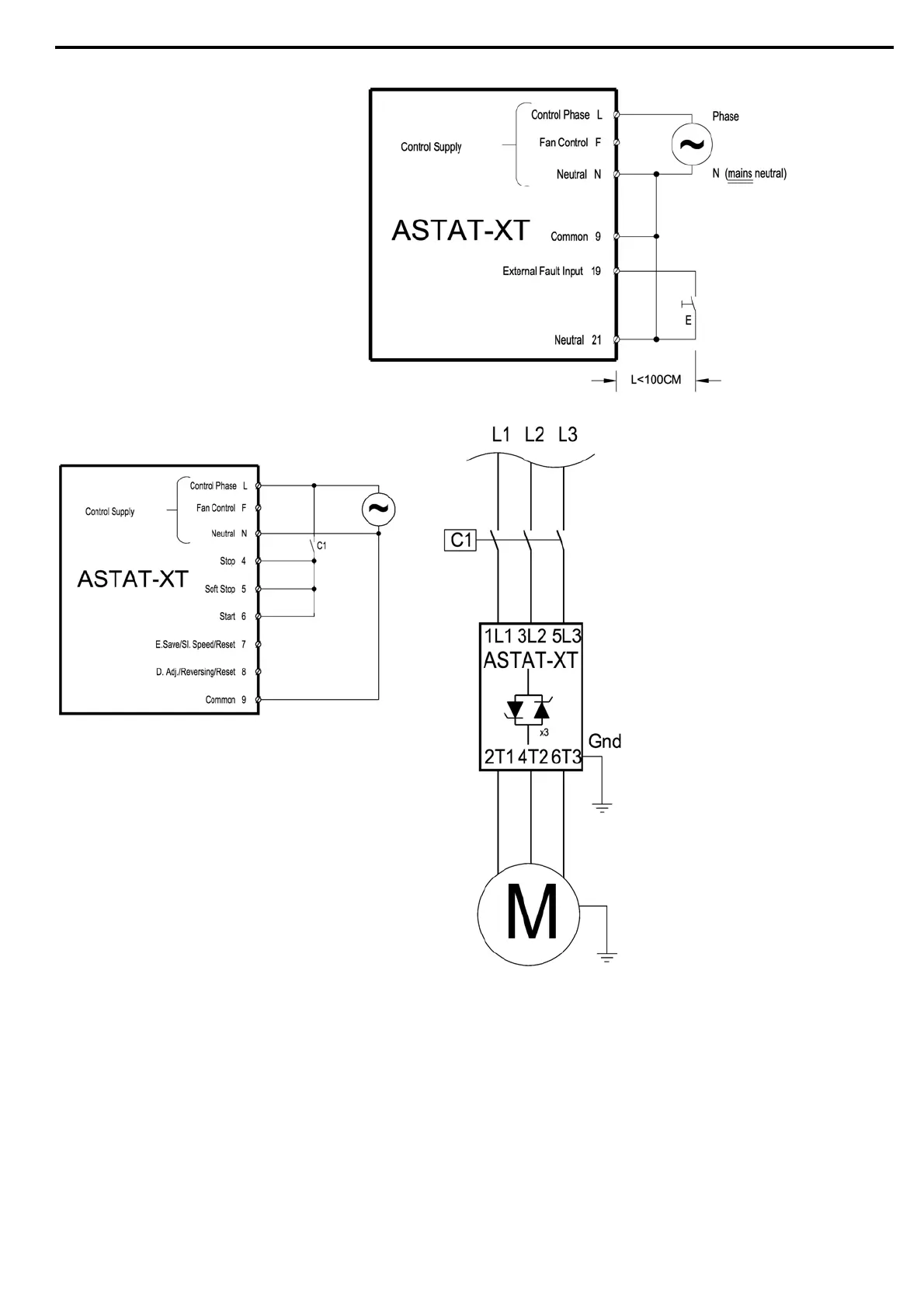
8.12 External Fault
Note:
Switch E can be
used as an External
Fault input only when terminal 21 is
connected to neutral or ground.
8.13 Line Contactor
Notes:
• Typical wiring when ASTAT-XT is retrofitted into an existing system to reduce modifications in existing
installations.
• Start signal is switched ON upon closure of the line contactor. The ASTAT-XT will operate as long as
the line contactor is energized.
• Control Supply obtained from mains must match the ASTAT-XT Control Supply voltage.
• It is recommended that terminals 1-3 are always connected to Control Supply voltage.
• Soft stop can not be applied for this wiring diagram. If soft stop is required, the line contactor can be
held by the Immediate Relay (RUN relay) contacts because the relay is de-energized only at the end
of the soft stop.
• Verify that N.O. contact C1 closes after the main contactor closes. ASTAT-XT requires 500 mSec. delay
for the start signal after the line contactor is closed. If it closes prior to that, Undervoltage FLT
will occur. It is recommended to use a time delay timer to prevent possible faults.

 Loading...


