3-58 G60 Generator Protection System GE Multilin
3.4 FIELD AND STATOR GROUND MODULES 3 HARDWARE
3
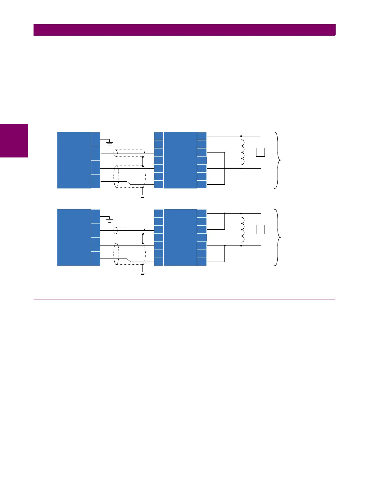
The following figure illustrates how to wire the GPM-F-HM module with the GPM-F-R resistor box for both single-point injec-
tion and double-point injection. To connect the units:
1. Externally short terminals C1 and C3 of the GPM-F-R high-voltage resistor box for both single-point injection and dou-
ble-point injection.
2. Shield the connection between F1 (terminal C2) on the GPM-F-HM field ground protection module and terminal A3 on
the GPM-F-R high-voltage resistor box module. Keep the connection length as short as possible, and do not exceed
10 meters.
3. Shield the connection between the F+ and F– pair (terminals C3 and C4) on the GPM-F-HM field ground protection
module and terminals A5 and A7 on the GPM-F-R high-voltage resistor box module. Keep the length as short as pos-
sible, and do not exceed 10 meters.
Figure 3–64: CONNECTING THE FIELD GROUND PROTECTION MODULE TO THE HIGH-VOLTAGE RESISTOR BOX
3.4.4 STATOR GROUND PROTECTION SYSTEM
Using 100% stator ground fault protection based on sub-harmonic injection, a 20 Hz voltage is injected to detect ground
faults at any point across 100% of the winding. The stator ground module works in combination the G60 to provide 100%
stator ground fault protection that is operational during generator start-up, running, and stopped conditions.
The stator ground protection system consists of three modules: the stator ground protection 20 Hz generator module
(GPM-S-G), the stator ground band pass filter module (GPM-S-B), and the stator ground protection CT (204-SD-43737).
The following figures show the mounting and dimensions (all dimensions are in inches).
With GPM-S, use a CT/VT module with Sensitive Ground capability (for example 8G, 8J, 8M, 8R) to connect stator ground
protection CT (204-SD-43737) input to the UR device.
)LHOGJURXQG
SURWHFWLRQ
PRGXOH
*30)+0
)LHOGJURXQG
SURWHFWLRQ
KLJKYROWDJH
UHVLVWRUER[
PRGXOH
*30)5
%
%
%
$
$
$
$
$
$
$
&
&
&
)
)²
)
&
&
&
&
)²
)
)LHOGJURXQG
SURWHFWLRQ
PRGXOH
*30)+0
&
&
&
&
&RQQHFWLRQIRU
VLQJOHSRLQW
LQMHFWLRQ
)LHOGJURXQG
SURWHFWLRQ
KLJKYROWDJH
UHVLVWRUER[
PRGXOH
*30)5
%
%
%
$
$
$
$
$
$
$
&
&
&
)
)
$&'5
&RQQHFWLRQIRU
GRXEOHSRLQW
LQMHFWLRQ
)
)²
)
(;
)
(;
)²
²
²

 Loading...


