GE Multilin G60 Generator Protection System 9-7
9 APPLICATION OF SETTINGS 9.1 SETTING EXAMPLE
9
The zone 3 reach will be set at 120% of the generator transient reactance. The time delay of this element should be com-
pared to the generator decrement curve to verify the adequacy of this setting.
(EQ 9.28)
(EQ 9.29)
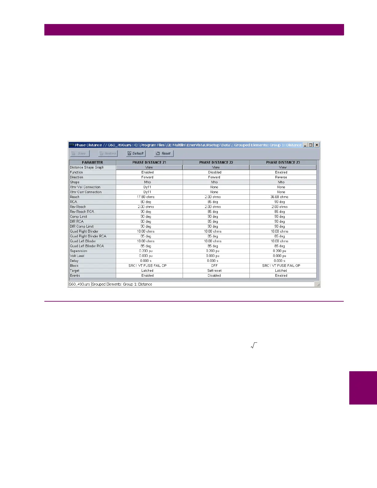
An mho shape has been chosen for this example. Therefore, the quadrilateral settings are left at their default values. Make
the following changes in EnerVista UR Setup or through the SETTINGS GROUPED ELEMENTS SETTING GROUP 1
DISTANCE PHASE DISTANCE Z1(3) menus:
9.1.11 STATOR GROUND FAULT
a) AUXILIARY OVERVOLTAGE
Stator ground fault protection is implemented with an overvoltage element connected at the generator neutral resistor. The
auxiliary overvoltage element will be used in this example. The auxiliary voltage input has previously been assigned to the
NEUTRL source. In this example the element will be set to protect 97% of the stator against ground faults.
(EQ 9.30)
The time delay should be longer than the longest normal clearing time for faults outside the generator zone. If the phase
VTs are wye-connected then this element should also be coordinated with VT secondary fuses to prevent false operations
for VT secondary ground faults. For the sample system a time delay of 1 second will be used. Make the following changes
in EnerVista UR Setup or through the
SETTINGS GROUPED ELEMENTS SETTING GROUP 1 VOLTAGE ELEMENTS
Generator impedance X
d
V
L
2
MVA
G
----------------
× j1.967
18()
2
211
--------------
× j3.01 primary ohms== =
Zone 3 reach 1.2 Generator impedance
CT ratio
VT ratio
---------------------
××=
1.2 j3.01×
1600
157.5
---------------
×= j36.68 secondary ohms=
PICKUP 0.03
Nominal Phase Ground Voltage–
Ground VT Primary
----------------------------------------------------------------------------------------
× 0.03
18000 3⁄
12000
----------------------------
× 0.026 pu===

 Loading...


