2-24 G60 Generator Protection System GE Multilin
2.2 SPECIFICATIONS 2 PRODUCT DESCRIPTION
2
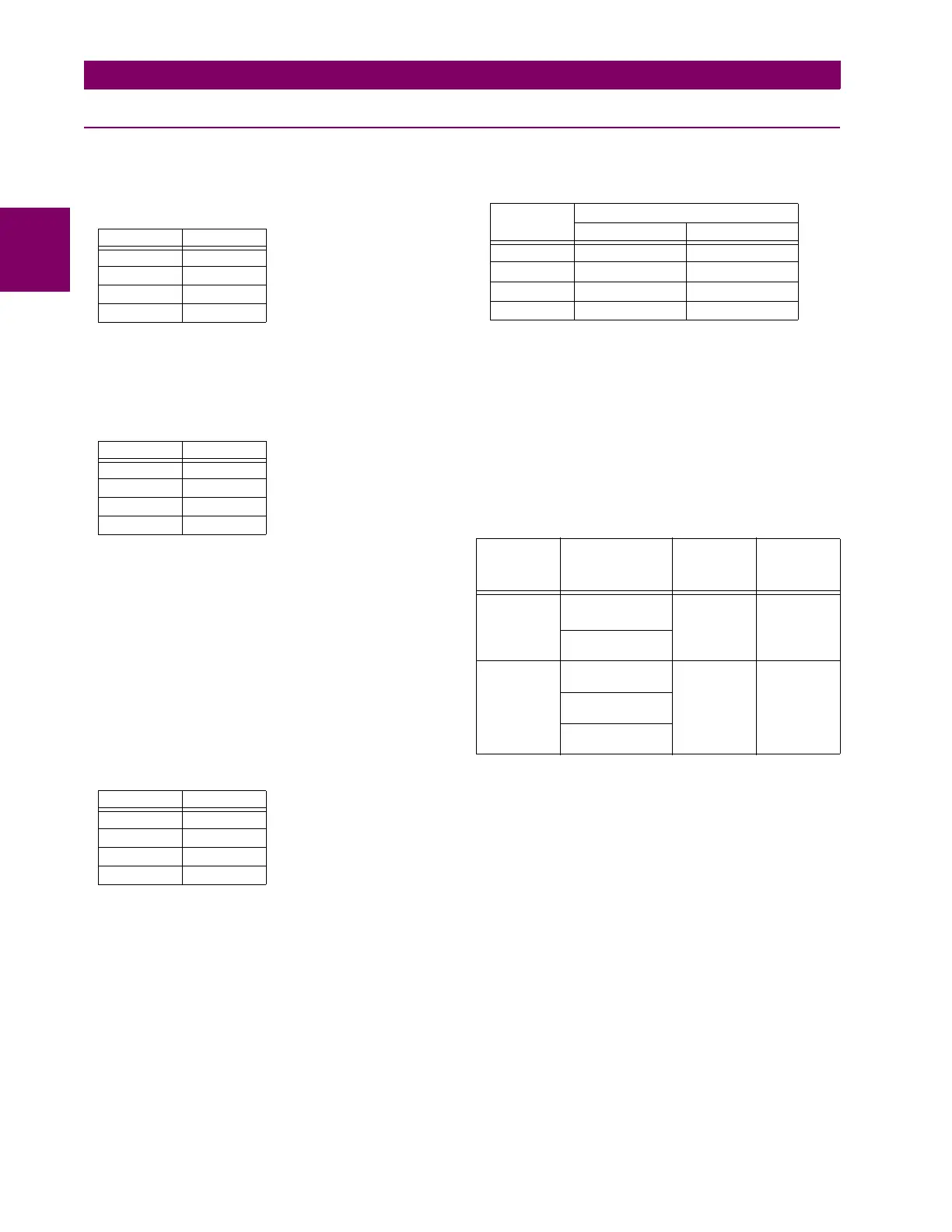
2.2.7 OUTPUTS
FORM-A RELAY
Make and carry for 0.2 s: 30 A as per ANSI C37.90
Carry continuous: 6 A
Break (DC inductive, L/R = 40 ms):
Operate time: < 4 ms
Contact material: silver alloy
LATCHING RELAY
Make and carry for 0.2 s: 30 A as per ANSI C37.90
Carry continuous: 6 A as per IEEE C37.90
Break (DC resistive as per IEC61810-1):
Operate time: < 4 ms
Contact material: silver alloy
Control: separate operate and reset inputs
Control mode: operate-dominant or reset-dominant
FORM-A VOLTAGE MONITOR
Applicable voltage: approx. 15 to 250 V DC
Trickle current: approx. 1 to 2.5 mA
FORM-A CURRENT MONITOR
Threshold current: approx. 80 to 100 mA
FORM-C AND CRITICAL FAILURE RELAY
Make and carry for 0.2 s: 30 A as per ANSI C37.90
Carry continuous: 8 A
Break (DC inductive, L/R = 40 ms):
Operate time: < 8 ms
Contact material: silver alloy
FAST FORM-C RELAY
Make and carry: 0.1 A max. (resistive load)
Minimum load impedance:
Operate time: < 0.6 ms
Internal Limiting Resistor: 100 Ω, 2 W
SOLID-STATE OUTPUT RELAY
Operate and release time: <100 μs
Maximum voltage: 265 V DC
Maximum continuous current: 5 A at 45°C; 4 A at 65°C
Make and carry:
for 0.2 s: 30 A as per ANSI C37.90
for 0.03 s 300 A
Breaking capacity:
CONTROL POWER EXTERNAL OUTPUT
(FOR DRY CONTACT INPUT)
Capacity: 100 mA DC at 48 V DC
Isolation: ±300 Vpk
REMOTE OUTPUTS (IEC 61850 GSSE/GOOSE)
Standard output points: 32
User output points: 32
DIRECT OUTPUTS
Output points: 32
DCMA OUTPUTS
Range: –1 to 1 mA, 0 to 1 mA, 4 to 20 mA
Max. load resistance: 12 kΩ for –1 to 1 mA range
12 kΩ for 0 to 1 mA range
600 Ω for 4 to 20 mA range
Accuracy: ±0.75% of full-scale for 0 to 1 mA range
±0.5% of full-scale for –1 to 1 mA range
±0.75% of full-scale for 0 to 20 mA range
99% Settling time to a step change: 100 ms
Isolation: 1.5 kV
Driving signal: any FlexAnalog quantity
Upper and lower limit for the driving signal: –90 to 90 pu in steps of
0.001
VOLTAGE CURRENT
24 V 1 A
48 V 0.5 A
125 V 0.3 A
250 V 0.2 A
VOLTAGE CURRENT
24 V 6 A
48 V 1.6 A
125 V 0.4 A
250 V 0.2 A
VOLTAGE CURRENT
24 V 1 A
48 V 0.5 A
125 V 0.3 A
250 V 0.2 A
INPUT
VOLTAGE
IMPEDANCE
2 W RESISTOR 1 W RESISTOR
250 V DC 20 KΩ 50 KΩ
120 V DC 5 KΩ 2 KΩ
48 V DC 2 KΩ 2 KΩ
24 V DC 2 KΩ 2 KΩ
Note: values for 24 V and 48 V are the same due to a
required 95% voltage drop across the load impedance.
UL508 Utility
application
(autoreclose
scheme)
Industrial
application
Operations/
interval
5000 ops /
1 s-On, 9 s-Off
5ops/
0.2 s-On,
0.2 s-Off
within 1
minute
10000 ops /
0.2 s-On,
30 s-Off
1000 ops /
0.5 s-On, 0.5 s-Off
Break
capability
(0 to 250 V
DC)
3.2 A
L/R = 10 ms
10 A
L/R = 40 ms
10 A
L/R = 40 ms
1.6 A
L/R = 20 ms
0.8 A
L/R = 40 ms

 Loading...


