GE Multilin G60 Generator Protection System 6-25
6 ACTUAL VALUES 6.3 METERING
6
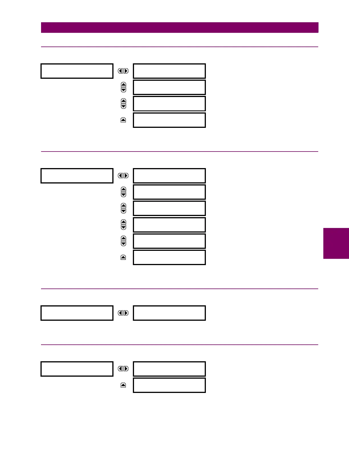
6.3.12 SUB-HARMONIC STATOR GROUND
PATH: ACTUAL VALUES METERING SUB-HARMONIC STATOR GROUND
Actual values related to sub-harmonic stator ground protection are displayed in this menu.
6.3.13 FIELD GROUND
PATH: ACTUAL VALUES METERING FIELD GROUND
Actual values related to field ground protection are displayed in this menu.
6.3.14 VOLTS PER HERTZ
PATH: ACTUAL VALUES METERING VOLTS PER HERTZ 1(2)
The volts per hertz actual values are displayed in this menu.
6.3.15 RESTRICTED GROUND FAULT
PATH: ACTUAL VALUES METERING RESTRICTED GROUND FAULT CURRENTS RESTRICTED GROUND FAULT 1(6)
The differential and restraint current values for the restricted ground fault element are displayed in this menu.
SUB-HARMONIC
STATOR GROUND
SH INJECTION VOLTS
0.000 V
MESSAGE
SH INJECTION AMPS
0.000 A
MESSAGE
SH CURRENT ANGLE
0°
MESSAGE
STATOR GND. RESIST:
> 500.000 k
FIELD
GROUND
FIELD GROUND RESIST
500 k
MESSAGE
FIELD VOLTAGE
0.0 V
MESSAGE
INJECTED VOLTAGE
0.000 V
MESSAGE
FAULT LOCATION
–10%
MESSAGE
FIELD GROUND
CURRENT: 0.00 mA
MESSAGE
FIELD CURRENT:
0.000 A
VOLTS PER HERTZ 1
VOLTS PER HERTZ 1:
0.000 pu
RESTRICTED
GROUND FAULT 1
RGF 1 DIFF Igd:
0.000 A
MESSAGE
RGF 1 RESTR Igr:
0.000 A

 Loading...


