GE Multilin G60 Generator Protection System 2-1
2 PRODUCT DESCRIPTION 2.1 INTRODUCTION
2
2 PRODUCT DESCRIPTION 2.1INTRODUCTION 2.1.1 OVERVIEW
The G60 Generator Protection System is a microprocessor based relay that provides protection, monitoring, control, and
recording functions for AC generators driven by steam, gas, or hydraulic turbine. Current, voltage and frequency protection
are provided along with fault diagnostics. Breaker fail function is provided for up to four breakers.
Voltage, current, and power metering is built into the relay as a standard feature. Current parameters are available as total
waveform RMS magnitude, or as fundamental frequency only RMS magnitude and angle (phasor).
Diagnostic features include an event recorder capable of storing 1024 time-tagged events, oscillography capable of storing
up to 64 records with programmable trigger, content and sampling rate, and data logger acquisition of up to 16 channels,
with programmable content and sampling rate. The internal clock used for time-tagging can be synchronized with an IRIG-
B signal, using the Simple Network Time Protocol (SNTP) over the Ethernet port, or using the Precision Time Protocol
(PTP). This precise time stamping allows the sequence of events to be determined throughout the system. Events can also
be programmed (via FlexLogic™ equations) to trigger oscillography data capture which may be set to record the measured
parameters before and after the event for viewing on a personal computer (PC). These tools significantly reduce trouble-
shooting time and simplify report generation in the event of a system fault.
Several options are available for communication. A faceplate RS232 port can be used to connect to a computer for the pro-
gramming of settings and the monitoring of actual values. The RS232 port has a fixed baud rate of 19.2 kbps. The rear
RS485 port allows independent access by operating and engineering staff. It can be connected to system computers with
baud rates up to 115.2 kbps. All serial ports use the Modbus RTU protocol. The 100Base-FX or 100Base-T Ethernet inter-
face provides fast, reliable communications in noisy environments. The Ethernet port supports IEC 61850, IEC 61850-90-5,
Modbus/TCP, and TFTP protocols, PTP (according to IEEE Std. 1588-2008 or IEC 61588), and allows access to the relay
via any standard web browser (G60 web pages). The IEC 60870-5-104 protocol is supported on the Ethernet port, and
DNP 3.0 and IEC 60870-5-104 cannot be enabled at the same time. The Ethernet port also supports the Parallel Redun-
dancy Protocol (PRP) of IEC 62439-3 (clause 4, 2012) when purchased as an option.
Settings and actual values can be accessed from the front panel or EnerVista software.
The G60 IEDs use flash memory technology which allows field upgrading as new features are added. The following Single
line diagram illustrates the relay functionality using ANSI (American National Standards Institute) device numbers.
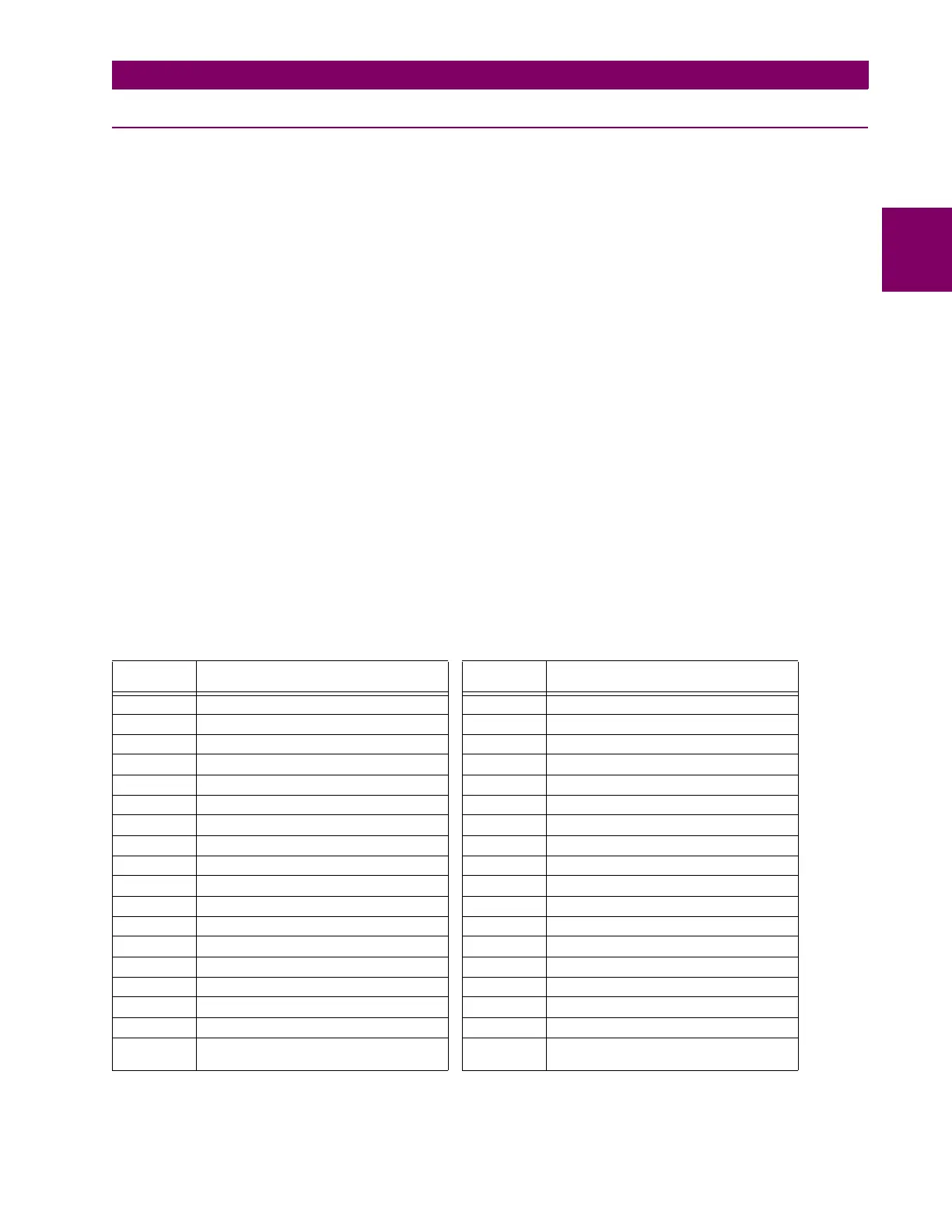
Table 2–1: ANSI DEVICE NUMBERS AND FUNCTIONS
DEVICE
NUMBER
FUNCTION DEVICE
NUMBER
FUNCTION
21P Phase distance backup 51N Neutral time overcurrent
24 Volts per hertz 59N Neutral overvoltage
25 Synchrocheck 59P Phase overvoltage
27P Phase undervoltage 59X Auxiliary overvoltage
27TN Third harmonic neutral undervoltage 59_2 Negative-sequence overvoltage
27X Auxiliary undervoltage 64F Field ground protection
32 Sensitive directional power 64S Sub-harmonic stator ground protection
40 Loss of excitation 64TN 100% stator ground
46 Generator unbalance 67_2 Negative-sequence directional overcurrent
49 Thermal overload protection (RTD) 67N Neutral directional overcurrent
50BF Breaker failure 67P Phase directional overcurrent
50G Ground instantaneous overcurrent 68 Power swing blocking
50N Neutral instantaneous overcurrent 78 Out-of-step protection
50P Phase instantaneous overcurrent 81O Overfrequency
50SP Split phase protection 81R Rate of change of frequency
50/27 Accidental energization 81U Underfrequency
51G Ground time overcurrent 87RGF Restricted ground fault
51PV Phase time overcurrent with voltage
restraint
87S Stator differential

 Loading...


