5-94 G60 Generator Protection System GE Multilin
5.4 SYSTEM SETUP 5 SETTINGS
5
b) VOLTAGE BANKS
PATH: SETTINGS SYSTEM SETUP AC INPUTS VOLTAGE BANK F5(M5)
Because energy parameters are accumulated, these values should be recorded and then reset
immediately prior to changing VT characteristics.
Two banks of phase/auxiliary VTs can be set, where voltage banks are denoted in the following format (X represents the
module slot position letter):
Xa, where X = {F, M} and a = {5}.
See the Introduction to AC sources section at the beginning of this chapter for additional details.
With VTs installed, the relay can perform voltage measurements as well as power calculations. Enter the PHASE VT F5 CON-
NECTION made to the system as “Wye” or “Delta”. An open-delta source VT connection would be entered as “Delta”.
The nominal PHASE VT F5 SECONDARY voltage setting is the voltage across the relay input terminals when nominal
voltage is applied to the VT primary.
For example, on a system with a 13.8 kV nominal primary voltage and with a 14400:120 volt VT in a delta connec-
tion, the secondary voltage would be 115; that is, (13800 / 14400) × 120. For a wye connection, the voltage value
entered must be the phase to neutral voltage which would be 115 / =66.4.
On a 14.4 kV system with a delta connection and a VT primary to secondary turns ratio of 14400:120, the voltage
value entered would be 120; that is, 14400 / 120.
5.4.2 POWER SYSTEM
PATH: SETTINGS SYSTEM SETUP POWER SYSTEM
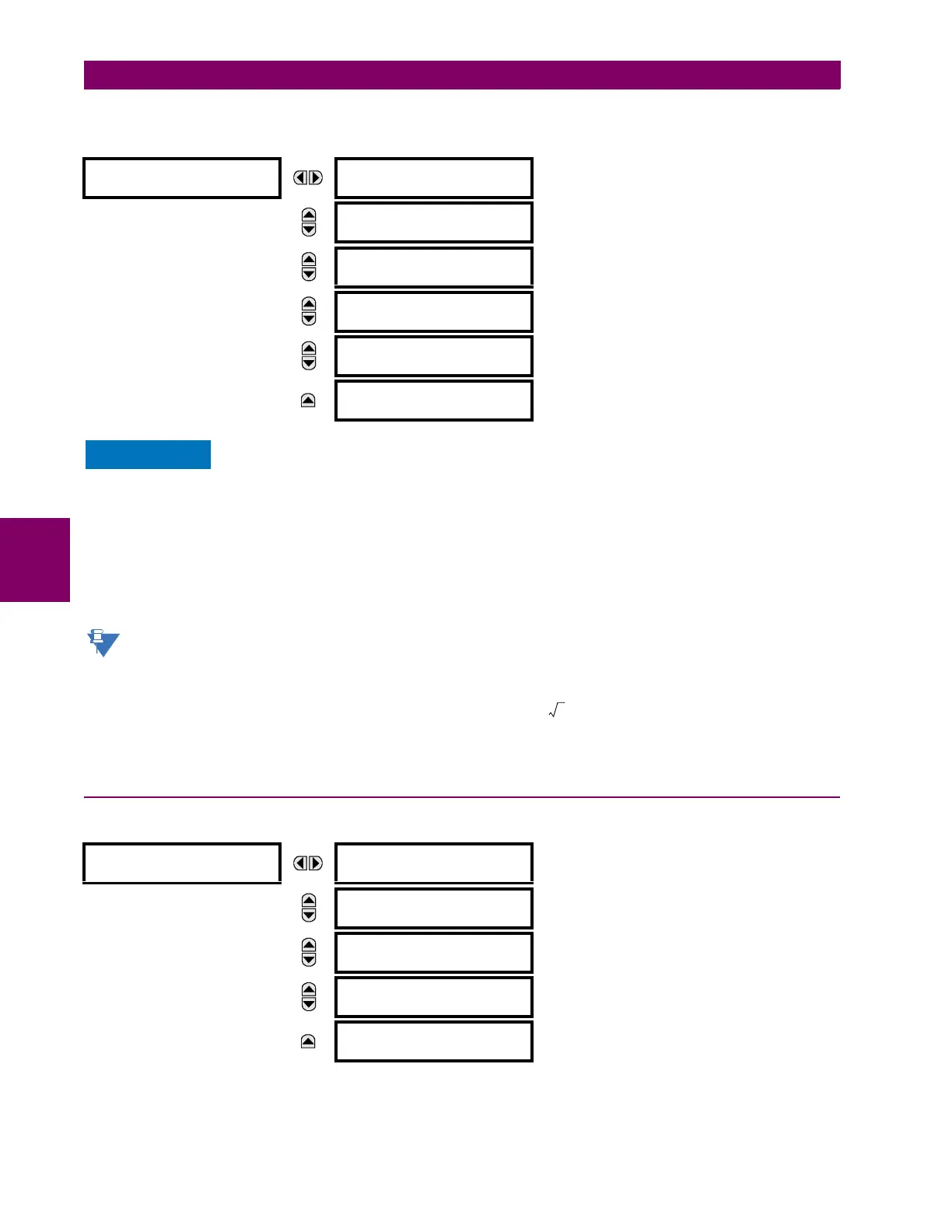
VOLTAGE BANK F5
PHASE VT F5
CONNECTION: Wye
Range: Wye, Delta
MESSAGE
PHASE VT F5
SECONDARY: 66.4 V
Range: 25.0 to 240.0 V in steps of 0.1
MESSAGE
PHASE VT F5
RATIO: 1.00 :1
Range: 1.00 to 24000.00 in steps of 0.01
MESSAGE
AUXILIARY VT F5
CONNECTION: Vag
Range: Vn, Vag, Vbg, Vcg, Vab, Vbc, Vca
MESSAGE
AUXILIARY VT F5
SECONDARY: 66.4 V
Range: 25.0 to 240.0 V in steps of 0.1
MESSAGE
AUXILIARY VT F5
RATIO: 1.00 :1
Range: 1.00 to 24000.00 in steps of 0.01
POWER SYSTEM
NOMINAL FREQUENCY:
60 Hz
Range: 25 to 60 Hz in steps of 1
MESSAGE
PHASE ROTATION:
ABC
Range: ABC, ACB
MESSAGE
REVERSE PH ROTATION:
Off
Range: FlexLogic operand
MESSAGE
FREQUENCY AND PHASE
REFERENCE: SRC 1
Range: SRC 1, SRC 2, SRC 3, SRC 4
MESSAGE
FREQUENCY TRACKING:
Enabled
Range: Disabled, Enabled

 Loading...


