8-4 G60 Generator Protection System GE Multilin
8.1 PHASE DISTANCE THROUGH POWER TRANSFORMERS 8 THEORY OF OPERATION
8
Equations from the “Current Transformation” and “Voltage Transformation” columns are used to derive inputs to the three
(AB, BC, and CA) phase distance elements. For example, if the CTs are located at the delta side of the Delta-Wye 11 trans-
former, and a given zone is set to look through the transformer into the system connected to the Wye winding, the CT loca-
tion setting for that zone shall be set to Dy11 and the relay would use
instead of a traditional for the AB
phase distance element.
The current supervision pickup setting applies to the currents specified in the “Current Transformation” columns.
A distance zone originates at the location of the VTs (regardless of the location of the CTs). For more information on set-
tings please refer to Chapter 9: Application of Settings.
8.1.2 EXAMPLE
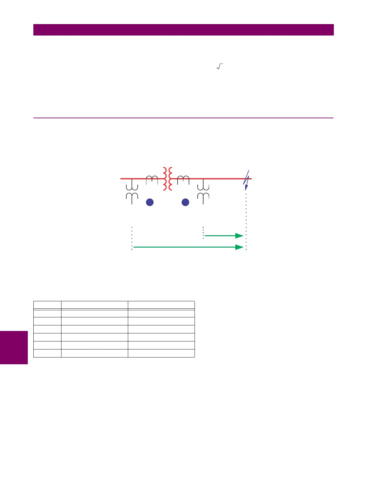
Consider the system shown below:
Figure 8–2: SAMPLE SYSTEM CONFIGURATION
Normally, in order to respond to the fault shown in the figure, a distance relay shall be applied at the relaying point X. The
relay input signals at this location are shown in the following table.
If installed at the location X, the relay would use the following input signals for its phase AB distance element:
V = V
AB
= 77.402 kV ∠57.5° primary or 29.49 V ∠57.5° secondary
I = I
A
– I
B
= 2.576 kA ∠–27.6° primary or 42.93 A ∠–27.6° secondary
And consequently it would see an apparent impedance of:
Z
app
= V / I = 30.05 Ω ∠85° primary or 0.687 Ω ∠85° secondary
INPUT PRIMARY SECONDARY
VA 100.4 kV ∠–7.32° 38.25 V ∠–7.32°
VB 97.23 kV ∠–53.4° 37.04 V ∠–53.4°
VC 181.8 kV ∠–150.0° 69.26 V ∠–150.0°
IA 1.288 kA ∠–27.6° 21.47 A ∠–27.6°
IB 1.288 kA ∠152.4° 21.47 A ∠152.4°
IC 0 0
837727A2.CDR
AB
wye, 330 lag°
0.688 85°Ω∠
2.57Ω∠88.4°
150 MVA, 10%
13.8kV/315kV
Z = 30.11 85°
L
Ω∠
VT = 315kV/120V
CT = 300:5
VT = 13.8kV/120V
CT = 8000:5
delta
HX

 Loading...


