GE Multilin G60 Generator Protection System 5-313
5 SETTINGS 5.9 TRANSDUCER INPUTS AND OUTPUTS
5
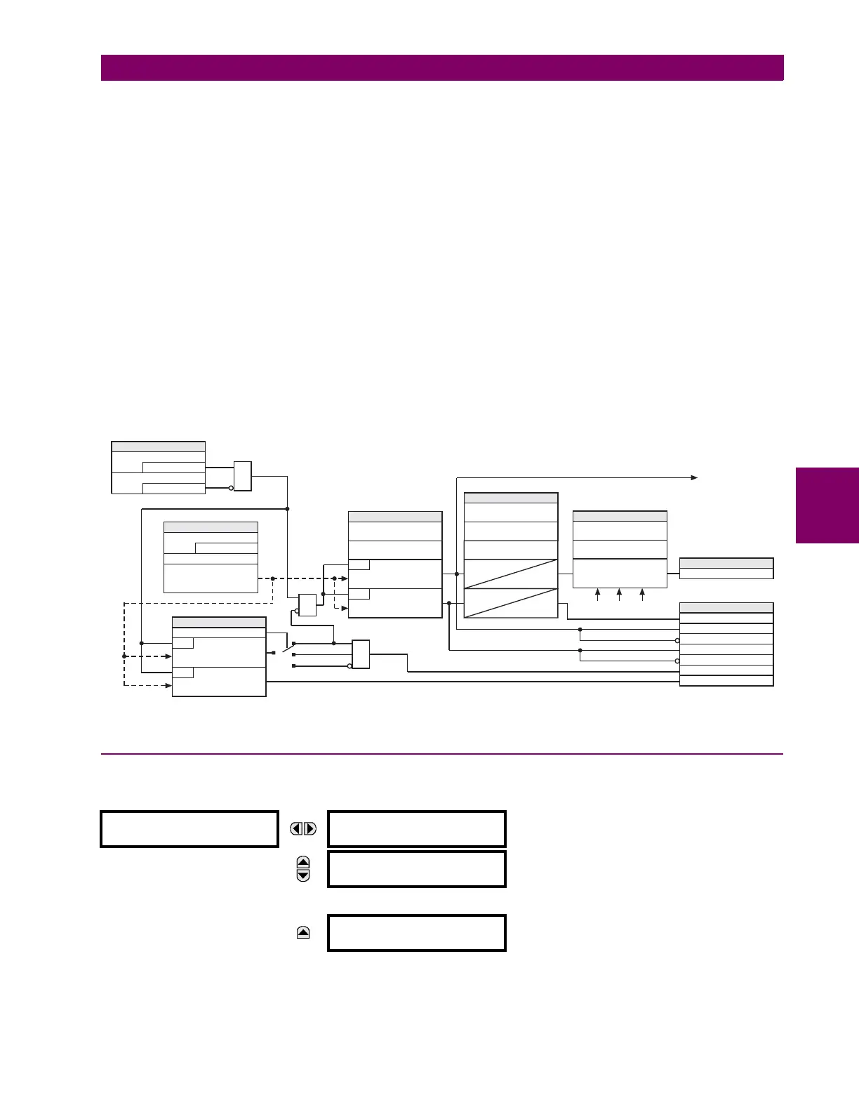
• RTD INPUT H1 TRIP RST DELAY: This setting specifies the reset delay to seal-in the trip signal.
• RTD INPUT H1 TRIP VOTING: This setting allows securing trip signal by voting with other RTDs. A value of “None”
indicates that element operates individually and no voting takes place.
A value of “Group” indicates that element is allowed to issue a trip if N – 1 of other RTDs of the same group pick up as
well (where N is the number of enabled RTDs from the group). For example, if three RTDs are assigned to the same
group, there should be at least one additional RTD of the same group picked up to issue a trip command.
The “RTD Inp H1” through “RTD Inp W8” values indicate that element is allowed to issue a trip if the corresponding
peer RTD is also picked up.
• RTD INPUT H1 OPEN: This setting allows monitoring an open RTD sensor circuit. If this functionality is not required,
then a value of “None” will disable monitoring and assertion of output operands.
If set to “Alarm”, the monitor will set an alarm when a broken sensor is detected.
If set to “Block”, the monitor will set an alarm and simultaneously block RTD operation when a broken sensor is
detected.
If targets are enabled, a message will appear on the display identifying the broken RTD. If this feature is used, it is rec-
ommended that the alarm be programmed as latched so that intermittent RTDs are detected and corrective action may
be taken.
• RTD INPUT H1 BLOCK: This setting is used to block RTD operation.
Figure 5–166: RTD INPUT PROTECTION LOGIC
5.9.3 RRTD INPUTS
a) MAIN MENU
PATH: SETTINGS TRANSDUCER I/O RRTD INPUTS
Menus are available to configure each of the remote RTDs.
RRTD INPUTS
RRTD 1
See page 5-314.
MESSAGE
RRTD 2
See page 5-314.
↓
MESSAGE
RRTD 12
See page 5-314.
None
Alarm
Block
From other RTDs for voting
To other RTDs for voting
SETTINGS
= Enabled
RTD INPUT H1 FUNCTION
Off=0
RTD INPUT H1 BLOCK
AND
=RTDInpH1
RTD INPUT H1 ID
SETTINGS
RTD INPUT H1 TYPE
Resistance to
temperature conversion
SETTING
RTD INPUT H1 OPEN
RUN
R 250°C³
RUN
R –50°C£
OR
AND
SETTINGS
RTD INPUT H1 TRIP
TEMPERATURE
RUN
temperature > TRIP PICKUP
RTD INPUT H1 ALARM
TEMPERATURE
RUN
temperature > ALARM PICKUP
SETTINGS
RTD INPUT H1 TRIP
PKP DELAY
RTD INPUT H1 TRIP
RST DELAY
T
PKP
0
T
PKP
T
DPO
RTD INPUT H1 ALARM
PKP DELAY
SETTINGS
RTD INPUT H1
APPLICATION
Voting logic
RTD INPUT H1 TRIP
VOTING
FLEXLOGIC OPERANDS
RTD Ip ALARM OP
RTD Ip TRIP PKP
RTDIpTRIPDPO
RTD Ip SHORTED
RTD Ip ALARM PKP
RTD Ip ALARM DPO
RTD Ip OPEN
FLEXLOGIC OPERAND
RTDIpTRIPOP
833019A2.CDR

 Loading...


