GE Multilin G60 Generator Protection System 3-11
3 HARDWARE 3.2 WIRING
3
3.2.2 DIELECTRIC STRENGTH
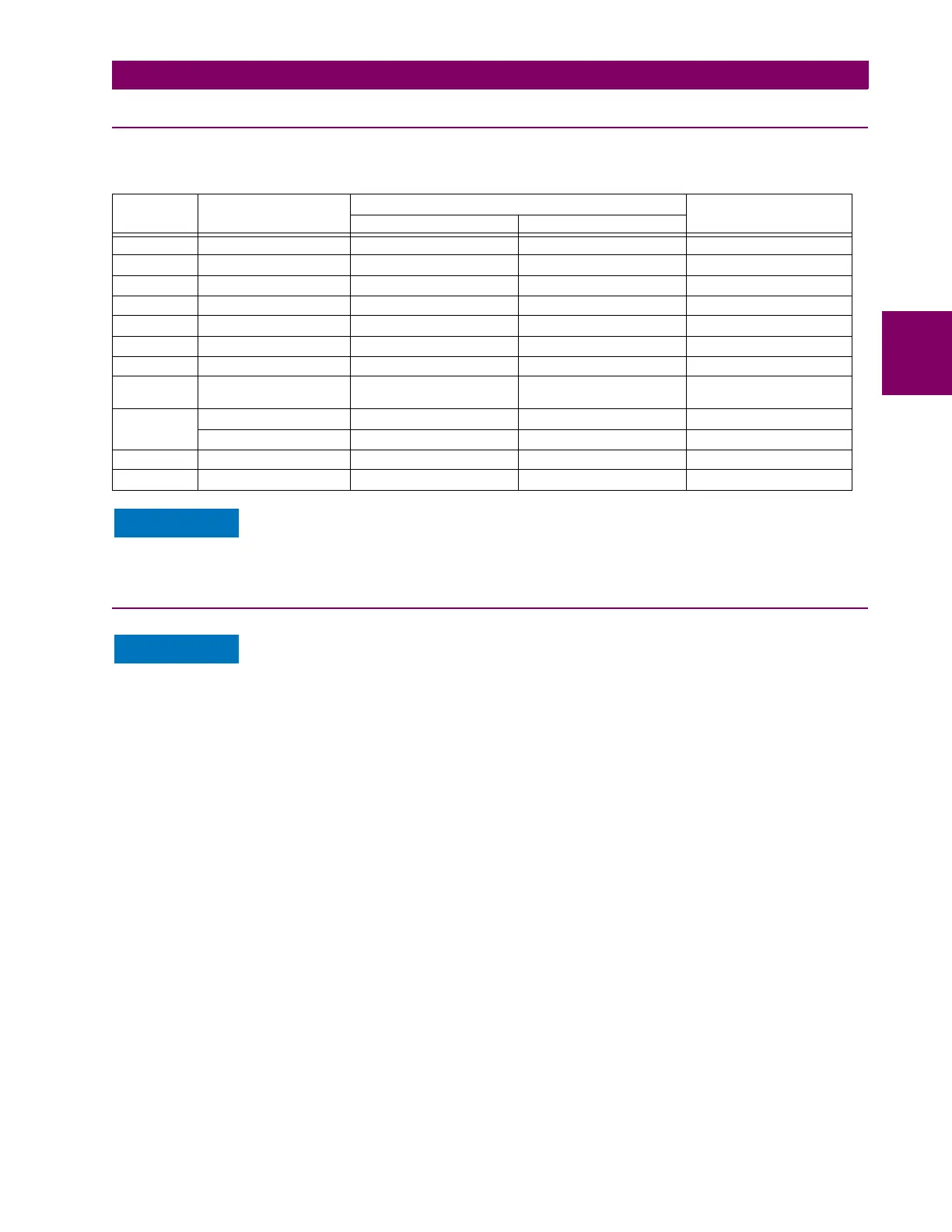
The dielectric strength of the UR-series module hardware is shown in the following table:
Filter networks and transient protection clamps are used in the hardware to prevent damage caused
by high peak voltage transients, radio frequency interference (RFI), and electromagnetic interference
(EMI). These protective components can be damaged by application of the ANSI/IEEE C37.90 spec-
ified test voltage for a period longer than the specified one minute.
3.2.3 CONTROL POWER
Control power supplied to the relay must be connected to the matching power supply range of the
relay. If voltage is applied to the wrong terminals, damage can occur.
The G60 relay, like almost all electronic relays, contains electrolytic capacitors. These capacitors are
well-known to deteriorate over time if voltage is not applied periodically. Deterioration can be avoided
by powering up the relay at least once a year.
The power supply module can be ordered for two possible voltage ranges, and the UR can be ordered with or without a
redundant power supply module option. Each range has a dedicated input connection for proper operation. The ranges are
as shown below (see the Technical specifications section of chapter 2 for additional details):
• Low (LO) range: 24 to 48 V (DC only) nominal
• High (HI) range: 125 to 250 V nominal
The power supply module provides power to the relay and supplies power for dry contact input connections.
The power supply module provides 48 V DC power for dry contact input connections and a critical failure relay (see the
Typical wiring diagram earlier). The critical failure relay is a form-C device that is energized once control power is applied
and the relay has successfully booted up with no critical self-test failures. If on-going self-test diagnostic checks detect a
critical failure (see the Self-test errors section in chapter 7) or control power is lost, the relay is de-energize.
For high reliability systems, the G60 has a redundant option in which two G60 power supplies are placed in parallel on the
bus. If one of the power supplies become faulted, the second power supply assumes the full load of the relay without any
interruptions. Each power supply has a green LED on the front of the module to indicate it is functional. The critical fail relay
of the module also indicates a faulted power supply.
Table 3–1: DIELECTRIC STRENGTH OF UR-SERIES MODULE HARDWARE
MODULE
TYPE
MODULE FUNCTION TERMINALS DIELECTRIC STRENGTH
(AC)
FROM TO
1 Power supply High (+); Low (+); (–) Chassis 2000 V AC for 1 minute
1 Power supply 48 V DC (+) and (–) Chassis 2000 V AC for 1 minute
1 Power supply Relay terminals Chassis 2000 V AC for 1 minute
2 Reserved N/A N/A N/A
3 Reserved N/A N/A N/A
4 Reserved N/A N/A N/A
5 Analog inputs/outputs All except 8b Chassis < 50 V DC
6 Digital contact inputs/
outputs
All Chassis 2000 V AC for 1 minute
7
G.703 All except 2b, 3a, 7b, 8a Chassis 2000 V AC for 1 minute
RS422 All except 6a, 7b, 8a Chassis < 50 V DC
8 CT/VT All Chassis 2000 V AC for 1 minute
9 CPU All Chassis 2000 V AC for 1 minute

 Loading...


