GE Multilin G60 Generator Protection System 5-317
5 SETTINGS 5.9 TRANSDUCER INPUTS AND OUTPUTS
5
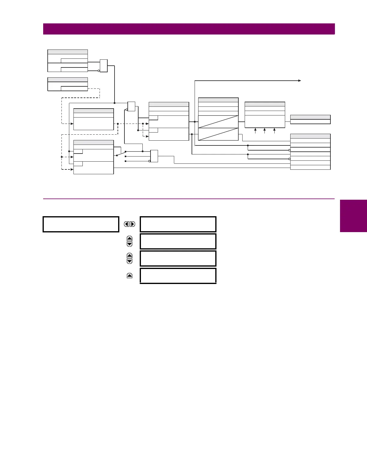
Figure 5–167: REMOTE RTD INPUT PROTECTION LOGIC
5.9.4 DCMA OUTPUTS
PATH: SETTINGS TRANSDUCER I/O DCMA OUTPUTS DCMA OUTPUT H1(W8)
Hardware and software is provided to generate DCmA signals that allow interfacing with external equipment. Specific hard-
ware details are contained in chapter 3. The DCmA output channels are arranged in a manner similar to transducer input or
CT and VT channels. The user configures individual channels with the settings shown below.
The channels are arranged in sub-modules of two channels, numbered 1 through 8 from top to bottom. On power-up, the
relay automatically generates configuration settings for every channel, based on the order code, in the same manner used
for CTs and VTs. Each channel is assigned a slot letter followed by the row number, 1 through 8 inclusive, which is used as
the channel number.
Both the output range and a signal driving a given output are user-programmable via the following settings menu (an exam-
ple for channel M5 is shown).
The relay checks the driving signal (x in equations below) for the minimum and maximum limits, and subsequently re-
scales so the limits defined as
MIN VAL and MAX VAL match the output range of the hardware defined as RANGE. The follow-
ing equation is applied:
(EQ 5.53)
DCMA OUTPUT H1
DCMA OUTPUT H1
SOURCE: Off
Range: Off, any analog actual value parameter
MESSAGE
DCMA OUTPUT H1
RANGE: –1 to 1 mA
Range: –1 to 1 mA, 0 to 1 mA, 4 to 20 mA
MESSAGE
DCMA OUTPUT H1
MIN VAL: 0.000 pu
Range: –90.000 to 90.000 pu in steps of 0.001
MESSAGE
DCMA OUTPUT H1
MAX VAL: 1.000 pu
Range: –90.000 to 90.000 pu in steps of 0.001
None
Alarm
Block
From other remote
RTDs for voting
To other remote RTDs
for voting
SETTINGS
Enabled = 1
Function
Off=0
Block
AND
=RRTD1
ID
SETTING
SETTING
Open
RUN
R > 1000 ohms
RUN
T –40°C£
OR
AND
SETTINGS
Trip Temperature
RUN
temperature > Trip Pickup
Alarm Temperature
RUN
temperature > Alarm Pickup
SETTINGS
Trip Pickup Delay
Trip Reset Delay
T
PKP
0
T
PKP
T
DPO
Alarm Pickup Delay
SETTINGS
Application
Voting logic
Trip Voting
FLEXLOGIC OPERANDS
RRTD 1 ALARM OP
RRTD 1 TRIP PKP
RRTD 1 TRIP DPO
RRTD 1 SHORTED
RRTD 1 ALARM PKP
RRTD 1 ALARM DPO
RRTD 1 OPEN
FLEXLOGIC OPERAND
REMOTE RTD 1 TRIP OP
833026A1.CDR
Type
Temperature read
from RRTD
SETTING
I
out
I
min
if x MIN VAL<
I
max
if x MAX VAL>
kx
MIN VAL–()I
min
+ otherwise
=

 Loading...


