9-10 G60 Generator Protection System GE Multilin
9.1 SETTING EXAMPLE 9 APPLICATION OF SETTINGS
9
9.1.12 OVEREXCITATION
This protection should be set to coordinate with the manufacturers excitation capability curves. For example system, the
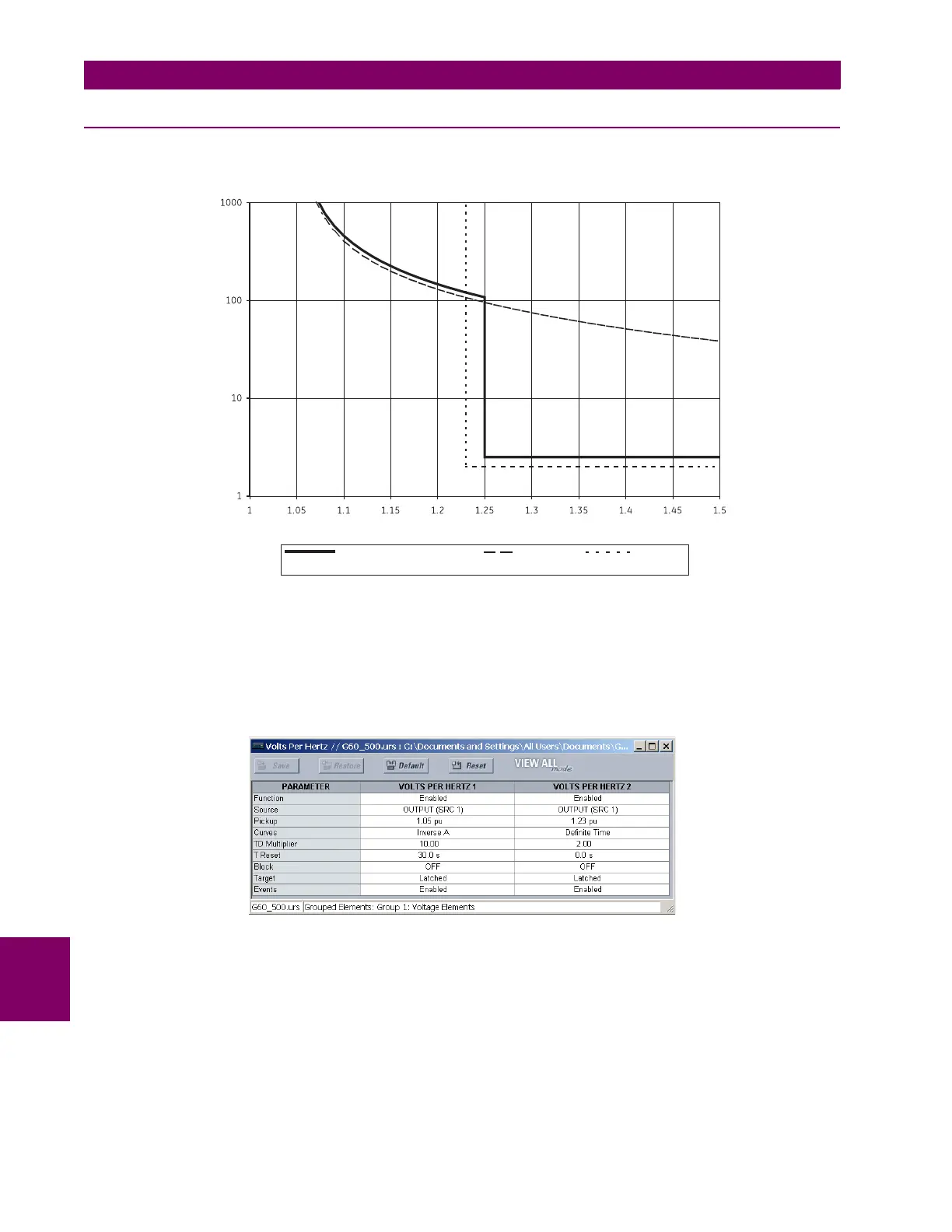
combined generator/GSU limit curve is shown:
Figure 9–4: GENERATOR/GSU LIMIT CURVE
Program the volts per hertz 1 element with an inverse characteristic (curve A), a pickup of 1.05, and a TDM of 40. Program
the volts per hertz 2 element with a definite time characteristic, a pickup of 1.23, and a time delay of 2 seconds. Both ele-
ments will issue a trip. The volts per hertz 1 pickup will be used to generate an alarm. Either source may be assigned in this
example. Make the following changes in EnerVista UR Setup or through the
SETTINGS GROUPED ELEMENTS SET-
TING GROUP 1 VOLTAGE ELEMENTS VOLTS/HZ 1(2) menus:
Volts per hertz (p.u.)
Combined generator/GSU
limit curve
Volts per
hertz 1
Volts per
hertz 2
Time (seconds)
830734A1.CDR

 Loading...


