9-6 G60 Generator Protection System GE Multilin
9.1 SETTING EXAMPLE 9 APPLICATION OF SETTINGS
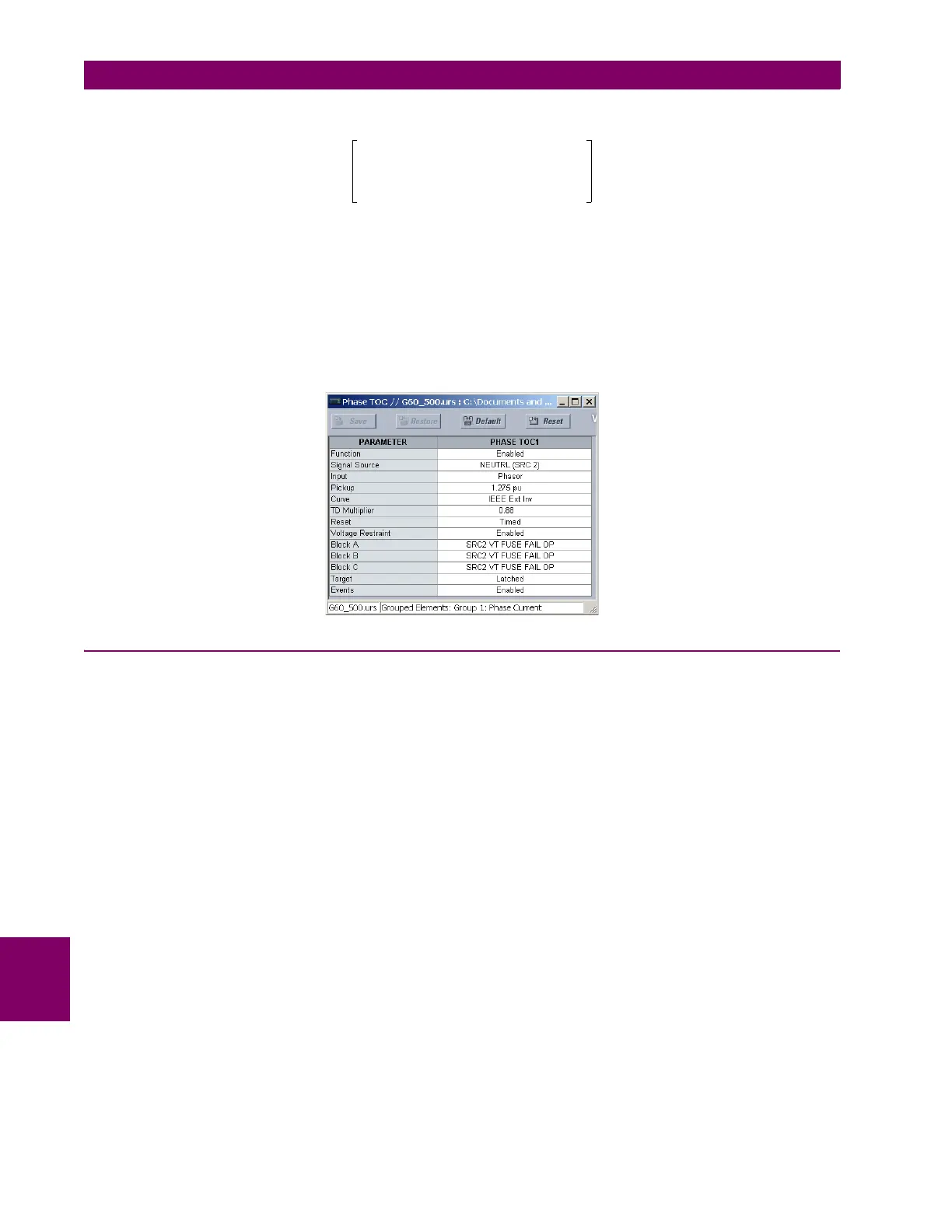
9
The equation for an IEEE extremely inverse curve is as follows:
(EQ 9.23)
where A = 28.2, B = 0.1217, and p = 2. Solving for TDM, we have:
(EQ 9.24)
Since this element will coordinate with system protections a timed reset is chosen. The element must be blocked for a VT
fuse failure. The neutral source will be chosen. Make the following changes in EnerVista UR Setup or through the SETTINGS
GROUPED ELEMENTS SETTING GROUP 1 PHASE CURRENT PHASE TOC1 menu:
9.1.10 BACKUP DISTANCE
This function provides time-delayed protection for system faults that have not been cleared by system protections and to
provide backup protection for stator faults.
The “Line” source will be used in this example to permit the application of a forward and reverse zone. The memory dura-
tion will be left at the default setting (10 cycles).
Zone 1 will look forward and cover the GSU and the transmission line leaving the station. Zone 3 will look in the reverse
direction and cover the stator winding. Zone 2 will not be used in this example. Both the VTs and the CTs are located on the
low voltage side of the GSU. The transformer vector diagram (see figure 9-1) shows this transformer to be Yd1. Conse-
quently, due to the location of instrument transformers, Dy11 is chosen for both the
XFMR VOL CONNECTION and XFMR CUR
CONNECTION
settings. There are no transformers in the reverse direction. Therefore “None” is chosen for both of the zone 3
transformer connection settings. The reach of the zone 1 element will be set at 120% of impedance of the GSU and the
transmission line. In the instance that there are multiple lines and/or multiple generators, the zone 1 reach must be
increased to compensate for the infeed effect.
(EQ 9.25)
(EQ 9.26)
(EQ 9.27)
T TDM
A
I
I
pickup
Pickup Reduction×
---------------------------------------------------------------------
p
1–
---------------------------------------------------------------------------------------
B+
×=
TDM
0.75
28.2
2.64
1.275 0.329×
------------------------------------
2
1–
------------------------------------------------------
0.1217+
-------------------------------------------------------------------------------
0.88==
Transformer impedance X
T
V
L
2
MVA
T
---------------
× j0.1
18()
2
200
--------------
× j0.162 primary ohms== =
Line impedance X
L
V
L
2
V
H
2
-------
× 15 j75+()
18()
2
138()
2
-----------------
× 0.255 j1.276 primary ohms+== =
Zone 1 reach 1.2 Transformer impedance Line impedance+()×
CT ratio
VT ratio
---------------------
×=
1.2 j0.162 0.255 j1.276++()
1600
157.5
---------------
××= 17.8 80° secondary ohms∠=

 Loading...


