GE Power Management
MM2 Motor Manager 2 A-1
APPENDIX A A.1 COMMISIONING SUMMARY
A
APPENDIX A MM2 COMMISSIONINGA.1 COMMISIONING SUMMARY A.1.1 DESCRIPTION
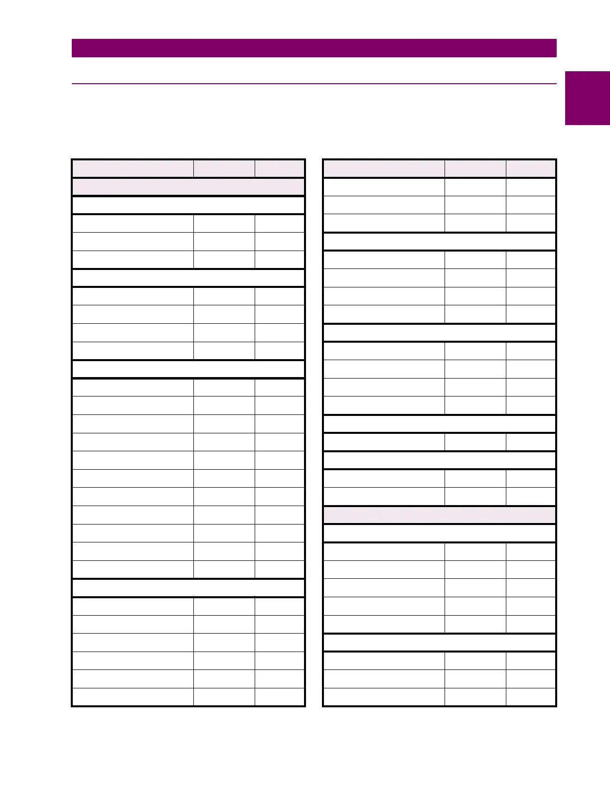
The following table lists all of the MM2 setpoints. Your application of the MM2 may not use all of
them.
Table A–1: MM2 COMMISSIONING (Sheet 1 of 8)
DESCRIPTION DEFAULT VALUE
S1: SYSTEM CONFIGURATION
COMMUNICATIONS
Communications Address Off
Baud Rate 9600
Parity None
MOTOR IDENTIFICATION
Motor Name Motor
Motor Rating Off
High Speed Motor Rating Off
System Supply 480 V
STARTER
Starter Type Off
Change Over Current 1.5 x FLC
Change Over Time 30 sec.
Transfer Time 10 sec.
High Speed Start Block Disable
Ramp Up Time 5 sec.
Ramp Down Time 5 sec.
Stage One Shorting Time 5 sec.
Contactor Sequence 1S-2S
Change Over Time (Autotrans) 5 sec.
Starts Per Hour 5
CT/VT INPUTS
Phase CT Primary Amps 100 A
Hi Speed Phase CT Primary A
100 A
Ground Fault CT Inputs
50:0.025 CBCT
Ground CT Primary Amps
100 A
50:0.025 Hi-Res Display
Disable
VT Primary Voltage Off
VT Connection Type Phase (A-N)
VT Secondary Voltage 120 V
Nominal Frequency 60 Hz
THERMISTOR
Cold Resistance 0.1 K
Ω
Hot Resistance 5.0 K
Ω
Thermistor Trip Disable
Thermistor Alarm Disable
FAULT MODE
Internal Fault Trip Enable
Serial Comms Failure Trip Off
Serial Comms Failure Alarm Off
Chg Command Mode on Alm Disable
PROGRAMMABLE MESSAGE
Programmable Message Sample Text
PREFERENCES
Default Message Display 10 sec.
Default Message Brightness 60%
S2: PROTECTION
MOTOR PROTECTION – THERMAL
Full Load Current 100 A
High Speed Full Load Current 100 A
Overload Pickup Level 1.00 x FLA
Overload Curve Number 4
Hot/Cold Curve Ratio 75%
MOTOR PROTECTION – GROUND FAULT
Ground Fault Alarm Level Off
Gnd Fault Alarm Delay On Run 10 sec.
Gnd Fault Alarm Dly On Start 10 sec.
Table A–1: MM2 COMMISSIONING (Sheet 2 of 8)
DESCRIPTION DEFAULT VALUE

 Loading...


