GE Power Management
MM2 Motor Manager 2 D-1
APPENDIX D D.1 ASYMMETRICAL CURRENT
D
APPENDIX D ASYMMETRICAL CURRENTD.1 ASYMMETRICAL CURRENT D.1.1 OVERVIEW
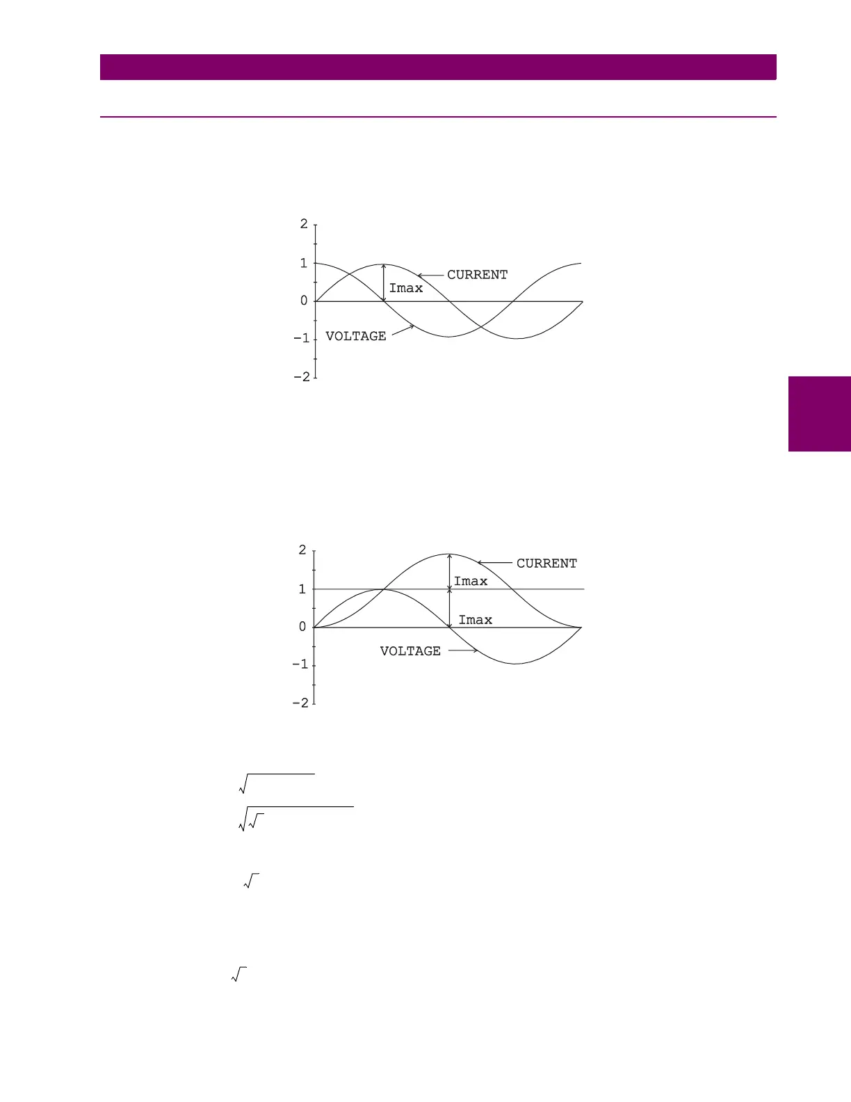
It is commonly known that current lags voltage by 90° when a voltage is applied to a purely inductive
load. As can be seen below, if the AC voltage is applied at a peak, the current will rise from 0 A to its
peak, 90° later in time. It may also be seen that during the time voltage completes a positive or neg-
ative half-cycle, current has made the transition from one peak to another.
Figure D–1: CURRENT-VOLTAGE PHASE DIFFERENCE
Thus, as shown in the second figure below, if voltage is applied at a zero crossing, current will make
the transition from minimum peak to maximum peak. Current of course, cannot instantaneously be at
its minimum value, it must begin at zero.
Thus it rises from zero to a value that is equal to 2 times the peak value (2
×
I
max
).
Depending on when the voltage is applied, the RMS current may vary by as much as 1.73 times.
Figure D–2: MAXIMUM CURRENT WHEN VOLTAGE APPLIED AT ZERO CROSSING
The asymmetrical RMS current is defined by:
Squaring both sides gives:
Which results in:
I
RMSassym
DC
2
AC
2
+=
2
I
RMS
⋅
2
I
RMS
2
+=
I
RMSassym
2
2
I
RMS
⋅()
2
I
RMS
2
+=
3
I
RMS
2
⋅()
=
I
RMSassym
3
I
RMS
⋅
=

 Loading...


