4-8 MM2 Motor Manager 2
GE Power Management
4.3 S2 PROTECTION 4 SETPOINTS
4
4.3 S2 PROTECTION 4.3.1 DESCRIPTION
This page is used to enter all information about the protection of the motor and the load. Setpoints
Page 2 is divided into four sections, MOTOR PROTECTION THERMAL, MOTOR PROTECTION
GROUND FAULT, MOTOR PROTECTION OPTIONS, LOAD PROTECTION and UNDER/OVER-
VOLTAGE PROTECTION.
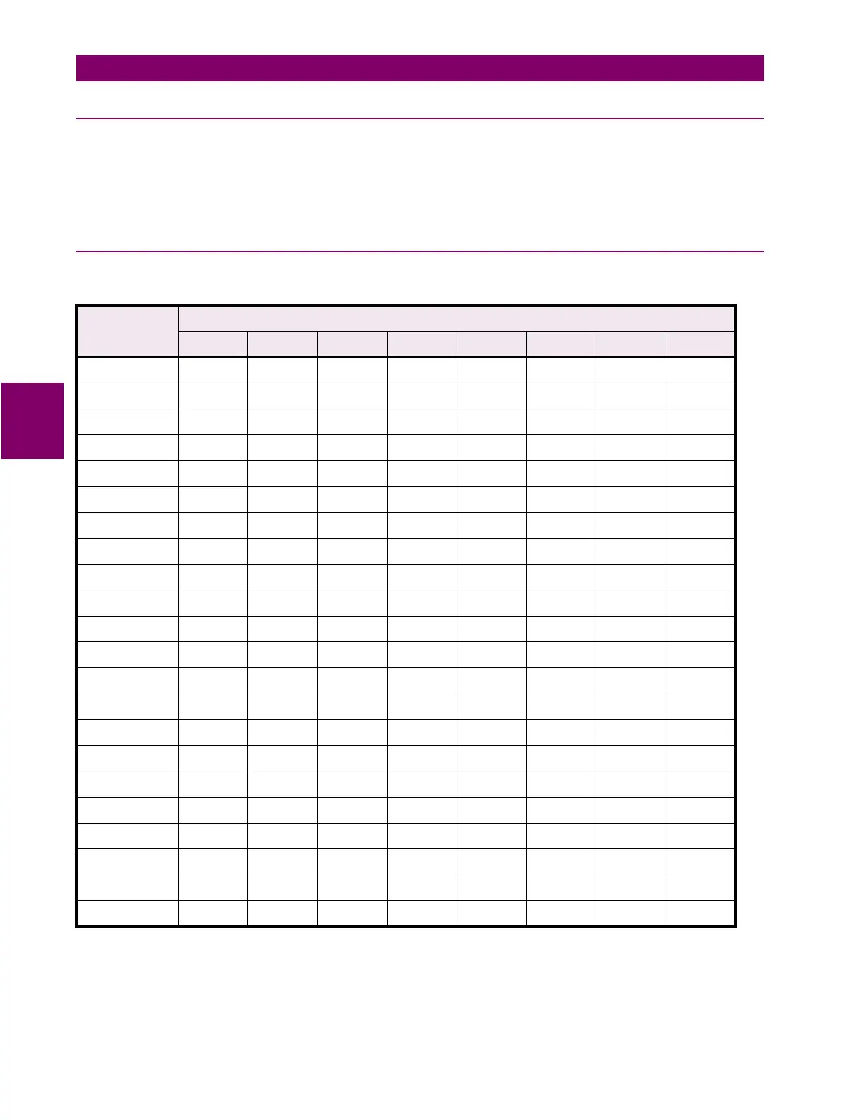
4.3.2 STANDARD OVERLOAD CURVES
The standard overload curves are shown in the following chart. Note that K+E 11” x 17” format of
time/overcurrent curves are available from factory upon request.
Table 4–1: STANDARD OVERLOAD CURVE TRIP TIMES (IN SECONDS)
OVERLOAD
LEVEL
CURVE NUMBER
1 2 3 4 5 6 7 8
1.05 7200 7200 7200 7200 7200 7682 10243 12804
1.10 416 833 1250 1666 2916 3750 5000 6250
1.20 198 397 596 795 1392 1789 2386 2982
1.30 126 253 380 507 887 1141 1521 1902
1.40 91 182 273 364 638 820 1093 1367
1.50 70 140 210 280 490 630 840 1050
1.75 42 84 127 169 297 381 509 636
2.00 29 58 87 116 204 262 350 437
2.25 21 43 64 86 150 193 258 323
2.50 16 33 50 66 116 150 200 250
2.75 13 26 39 53 93 119 159 199
3.00 10 21 32 43 76 98 131 164
3.50 7.8152331546993116
4.00 5.811172340526987
4.50 4.5 9 13 18 31 40 54 68
5.00 3.6 7.2 10 14 25 32 43 54
5.50 3 6 9 12 20 26 35 44
6.00 2.557.51017223037
6.50 2.1 4.2 6.3 8.4 14 19 25 31
7.00 1.8 3.6 5.4 7.2 12 16 21 27
7.50 1.6 3.2 4.8 6.4 11 14 19 23
8.00 1.4 2.8 4.2 5.6 9.8 12 16 20

 Loading...


