5-108 T35 TRANSFORMER PROTECTION SYSTEM – INSTRUCTION MANUAL
PRODUCT SETUP CHAPTER 5: SETTINGS
5
Commands are received as General Command (Type Identification 20). The user can configure the action to perform when
an ASDU command comes.
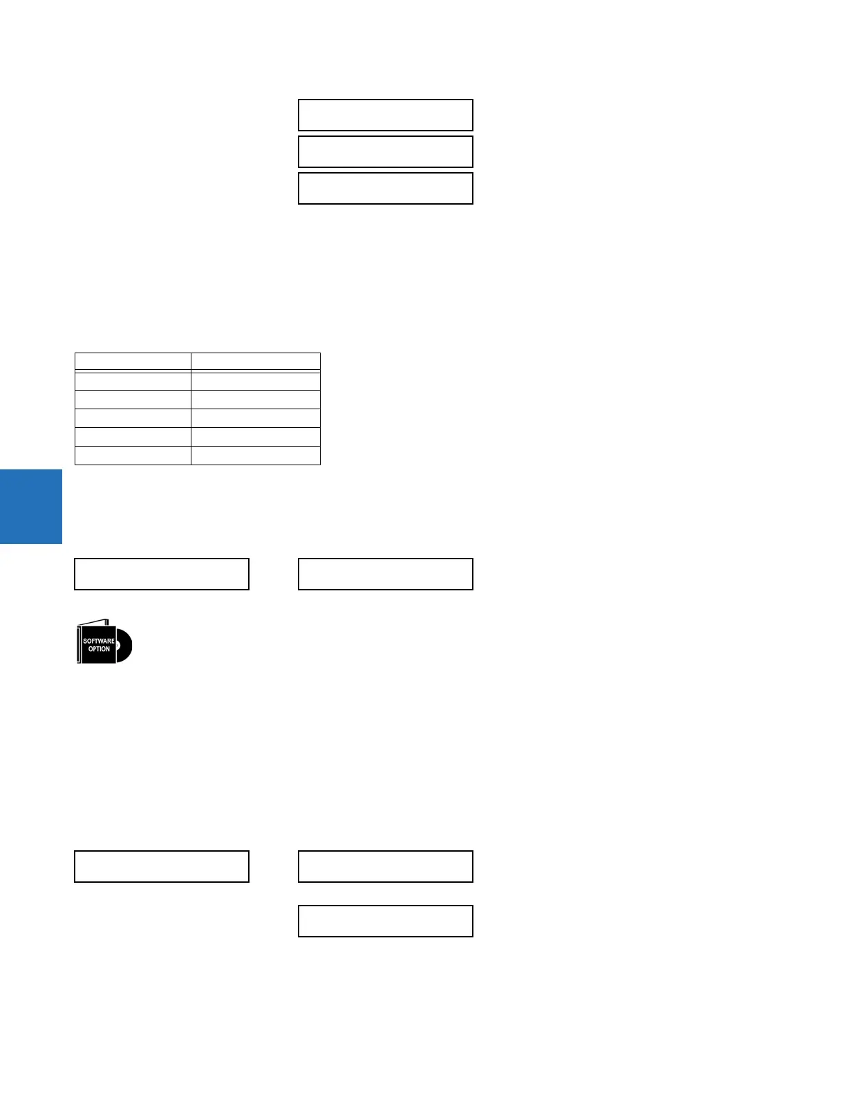
A list of available mappings is provided on the T35. This includes 64 virtual inputs (see the following table). The ON and OFF
for the same ASDU command can be mapped to different virtual inputs.
Each command is identified by the unique combination made by the function type (FUN) and information number (INF). If
the master sends an ASDU command that does not have the FUN and INF of any configured command, the relay rejects it.
Table 5-12: Commands mapping table
For any change to take effect, restart the relay.
5.3.5.18 USB port
SETTINGS PRODUCT SETUP COMMUNICATIONS USB 2.0
This setting enables/disables the USB port on the graphical front panel. When the port function is "Enabled," a standard
USB serial cable allows a computer running the EnerVista UR Setup software to retrieve, display, and write settings either
individually or collectively, to display status and actual values, to initiate controls, and to retrieve and display event records,
oscillography records, data logger records, and disturbance records. Installation of the EnerVista software automatically
installs the drivers required to use this USB port.
DNP is not available using the USB port on the graphical front panel.
5.3.6 Modbus user map
SETTINGS PRODUCT SETUP MODBUS USER MAP
COMMAND 31 INF:
0
Range: 0 to 255 in steps of 1
COMMAND 31 ON:
Off
Range: Virtual input
COMMAND 31 OFF:
Off
Range: Virtual input
Description Value
Off 0
Virtual Input 1 1
Virtual Input 2 2
... ...
Virtual Input 64 64
USB 2.0
USB DEVICE PORT
FUNCTION: Enabled
Range: Disabled, Enabled
This setting applies to the USB port on the graphical front panel.
MODBUS USER MAP
ADDRESS 1: 0
VALUE: 0
Range: 0 to 65535 in steps of 1
ADDRESS 256: 0
VALUE: 0
Range: 0 to 65535 in steps of 1
 Loading...


