6-10 T35 TRANSFORMER PROTECTION SYSTEM – INSTRUCTION MANUAL
STATUS CHAPTER 6: ACTUAL VALUES
6
6.3.18 Teleprotection channel tests
ACTUAL VALUES STATUS TELEPROT CH TESTS
The status information for two channels is shown here.
CHANNEL 1 STATUS — This represents the receiver status of each channel. If the value is “OK,” teleprotection is enabled and
data is being received from the remote terminal; If the value is “FAIL,” teleprotection enabled and data is not being received
from the remote terminal. If “n/a,” teleprotection is disabled.
CHANNEL 1 LOST PACKETS — Data is transmitted to the remote terminals in data packets at a rate of two packets per cycle.
The number of lost packets represents data packets lost in transmission; this count can be reset to 0 through the
COMMANDS CLEAR RECORDS menu.
VALIDITY OF CHANNEL CONFIGURATION — This value displays the current state of the communications channel identification
check, and hence validity. If a remote relay ID does not match the programmed ID at the local relay, the “FAIL” message
displays. The “N/A” value appears if the local relay ID is set to a default value of “0,” the channel is failed, or if the
teleprotection inputs/outputs are not enabled.
6.3.19 Remaining connection status
ACTUAL VALUES STATUS COMM STATUS REMAINING CONNECT
These values specify the remaining number of TCP connections still available for each protocol. The display depends on the
options applicable to your device. Each time a connection is used, the remaining number of connections decrements.
When released, the remaining number of connections increments. If no connection is made over the specific protocol, the
number equals the maximum number available for the specific protocol.
For example, the maximum number of Modbus TCP connections is 4. Once an EnerVista session is opened on a computer
connected to the UR over Ethernet, the Modbus TCP status shows 3. If the EnerVista application is closed, the Modbus TCP
status shows 4.
For the graphical front panel, the remaining connections refer to TCP connections only.
MMS TCP — The number of IEC 61850 connections remaining.
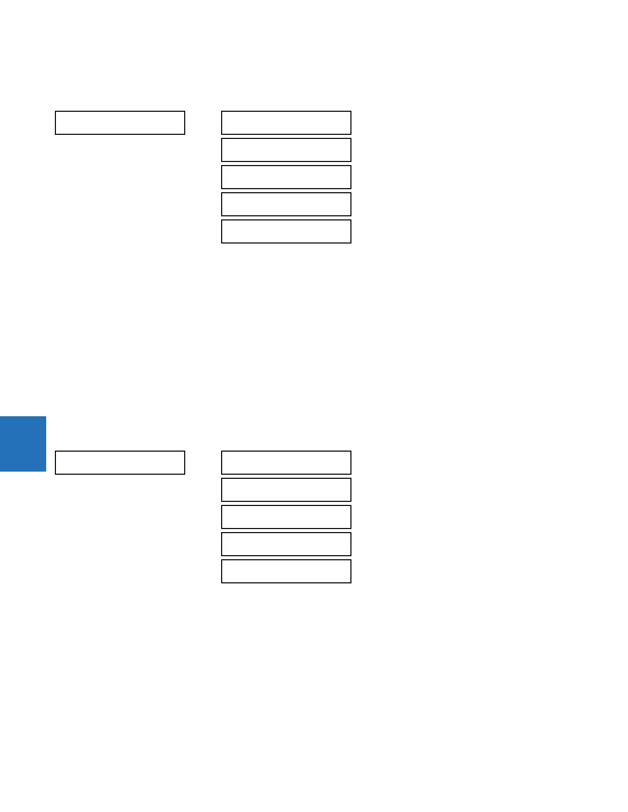
TELEPROT CH TESTS
CHANNEL 1
STATUS: n/a
Range: n/a, FAIL, OK
CHANNEL 1 LOST
PACKETS: 1
Range: 1 to 65535 in steps of 1
CHANNEL 2
STATUS: n/a
Range: n/a, FAIL, OK
CHANNEL 2 LOST
PACKETS: 1
Range: 1 to 65535 in steps of 1
VALIDITY OF CHANNEL
CONFIGURATION: FAIL
Range: n/a, FAIL, OK
COMM STATUS
REMAINING CONNECT
MMS TCP(max 5)
5
Range: 0 to 5
MODBUS TCP (max 4)
4
Range: 0 to 4
DNP TCP(max 2)
2
Range: 0 to 2
IEC-104 TCP(max 2)
2
Range: 0 to 2
SFTP (max 4)
4
Range: 0 to 4
 Loading...


