CHAPTER 5: SETTINGS CONTROL ELEMENTS
T35 TRANSFORMER PROTECTION SYSTEM – INSTRUCTION MANUAL 5-223
5
Igd = abs(3 × 0.0333 + 0.05) = 0.15 pu, IR0 = abs(3 × 0.033 – (0.05)) = 0.05 pu, IR2 = 3 × 0.033 = 0.10 pu,
IR1 = 1.033 / 8 = 0.1292 pu, and Igr = 0.1292 pu
Despite very low fault current level, the differential current is above 100% of the restraining current.
Example 5: Internal low-current, high-load single-line-to-ground fault with no feed from the ground
Given the following inputs: IA = 1.10 pu ∠0°, IB = 1.0 pu ∠–120°, IC = 1.0 pu ∠120°, and IG = 0.0 pu ∠0°
The relay calculates the following values:
I_0 = 0.033 pu ∠0°, I_2 = 0.033 pu ∠0°, and I_1 = 1.033 pu ∠0°
Igd = abs(3 × 0.0333 + 0.0) = 0.10 pu, IR0 = abs(3 × 0.033 – (0.0)) = 0.10 pu, IR2 = 3 × 0.033 = 0.10 pu,
IR1 = 1.033 / 8 = 0.1292 pu, and Igr = 0.1292 pu
Despite very low fault current level the differential current is above 75% of the restraining current.
Example 6: Internal high-current single-line-to-ground fault with no feed from the ground
Given the following inputs: IA = 10 pu ∠0°, IB = 0 pu, IC = 0 pu, and IG = 0 pu
The relay calculates the following values:
I_0 = 3.3 pu ∠0°, I_2 = 3.3 pu ∠0°, and I_1 = 3.3 pu ∠0°
Igd = abs(3 × 3.3 + 0.0) = 10 pu, IR0 = abs(3 × 3.3 – (0.0)) = 10 pu, IR2 = 3 × 3.3 = 10 pu, IR1 = 3 × (3.33 – 3.33) = 0 pu, and
Igr = 10 pu
The differential current is 100% of the restraining current.
5.8 Control elements
5.8.1 Overview
Control elements are used for control rather than protection. See the Introduction to Elements section at the beginning of
this chapter for information.
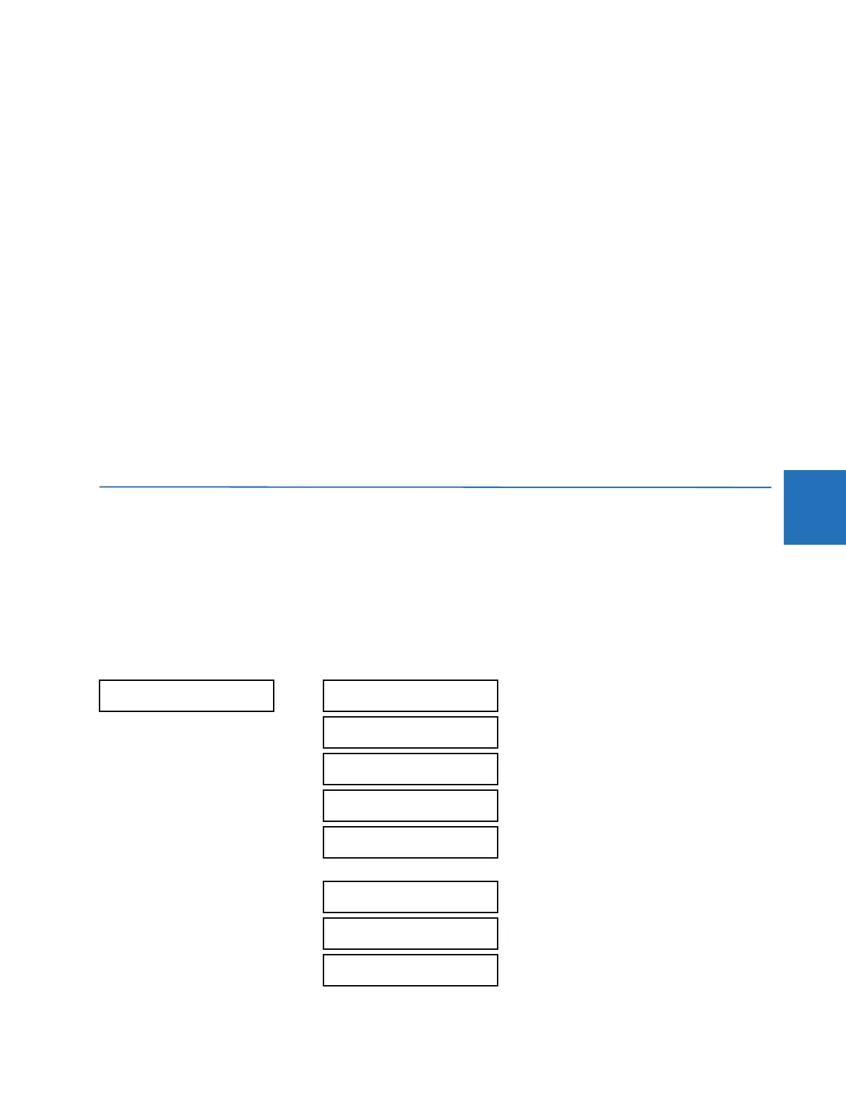
5.8.2 Trip bus
SETTINGS CONTROL ELEMENTS TRIP BUS TRIP BUS 1(6)
TRIP BUS 1
TRIP BUS 1
FUNCTION: Disabled
Range: Enabled, Disabled
TRIP BUS 1 BLOCK:
Off
Range: FlexLogic operand
TRIP BUS 1 PICKUP
DELAY: 0.00 s
Range: 0.00 to 600.00 s in steps of 0.01
TRIP BUS 1 RESET
DELAY: 0.00 s
Range: 0.00 to 600.00 s in steps of 0.01
TRIP BUS 1 INPUT 1:
Off
Range: FlexLogic operand
TRIP BUS 1 INPUT 16:
Off
Range: FlexLogic operand
TRIP BUS 1
LATCHING: Disabled
Range: Enabled, Disabled
TRIP BUS 1 RESET:
Off
Range: FlexLogic operand
 Loading...


