8-14 T35 TRANSFORMER PROTECTION SYSTEM – INSTRUCTION MANUAL
OVEREXCITATION INHIBIT TEST CHAPTER 8: COMMISSIONING
8
8.4 Overexcitation inhibit test
8.4.1 Overexcitation inhibit test procedure
The Overexcitation Inhibit Test requires a secondary injection from a source capable of producing an adjustable 5th
harmonic component. Use the appropriate commissioning tables at the end of this chapter to record values.
This procedure is based upon the example provided in the Differential Characteristic Test Example section. The transformer
parameters are as follows:
• Transformer — Y/y0°, 230/69 kV, CT1 (300:1), CT2 (1000:1)
• 5th Harmonic Setting — 10%
1. Connect the relay test set to inject current into the Winding 1 Phase A CT input.
2. Inject a current into the relay until the biased Differential element operates.
3. Confirm that ONLY the differential element has operated.
4. Increase the 5th harmonic content level until the element drops out. Record this value as the Overexcitation Inhibit
Level Pickup.
5. Gradually decrease the harmonic content level until the element picks up. Record this value as the Overexcitation
Inhibit Level Dropout.
6. Switch off the current.
7. Repeat steps 1 through 6 for phases B and C.
8. Repeat steps 1 through 7 for winding 2 (and windings 3 and 4 if necessary).
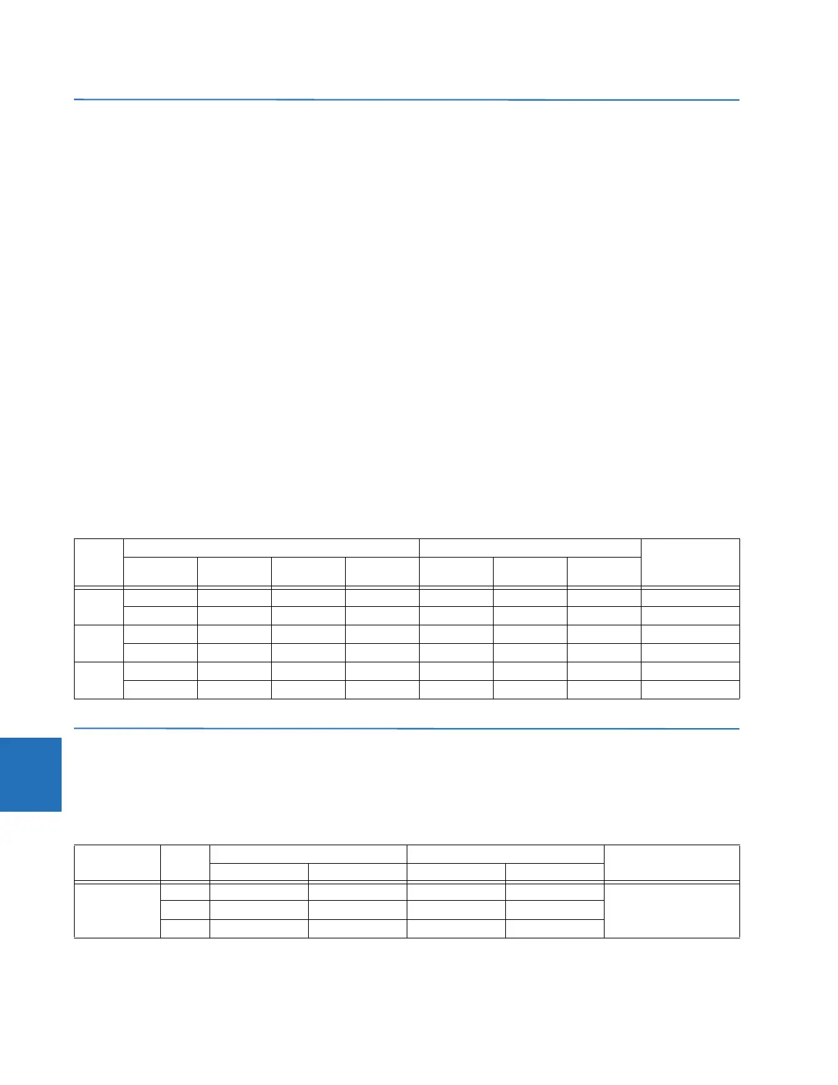
Table 8-4: Overexcitation inhibit test summary
8.5 Blank test tables
8.5.1 Differential restraint tests
Table 8-5: Differential characteristic test table
Phase Injected Displayed Status
W1 Current W1 5th
Harmonic
W2 Current W2 5th
Harmonic
I
d
5th
Harmonic
I
r
A1 A ∠0° 8% 0 A ∠0° 0 1 pu 8% 1 pu Operate
1 A ∠0° 10% 0 A ∠0° 0 1 pu 10% 1 pu Block
B4 A ∠0° 8.5% 2 A ∠–180° 9% 2 pu 8% 4 pu Operate
4 A ∠0° 9.5% 2 A ∠–180° 9% 2 pu 10% 4 pu Block
C2 A ∠0° 9% 4 A ∠–180° 8.5% 2 pu 8% 4 pu Operate
2 A ∠0° 9% 4 A ∠–180° 9.5% 2 pu 10% 4 pu Block
Test Phase Injected current Displayed current Status
W1 Current W2 Current Differential Restraint
Balanced
Condition
A Not Applicable
B
C
 Loading...


