CHAPTER 8: COMMISSIONING DIFFERENTIAL CHARACTERISTIC TEST EXAMPLES
T35 TRANSFORMER PROTECTION SYSTEM – INSTRUCTION MANUAL 8-9
8
4. Read the following differential and restraint current values in the T35 actual values menu.
5. The actual I
d
/I
r
ratio is now 95.9%. Verify that the element operates correctly.
8.2.2.7 Summary
The tests described the principles of testing the differential element for all regions from the operating characteristic.
For verification of more points, consider adjusting the magnitude of the restraint current I
r
to the required portion of the
characteristic and change the other current to vary I
d
until the relay operates. Use the Excel tool to compare the actual
and expected operating values.
A blank result table is provided at the end of this chapter for convenience.
8.2.3 Test example 2
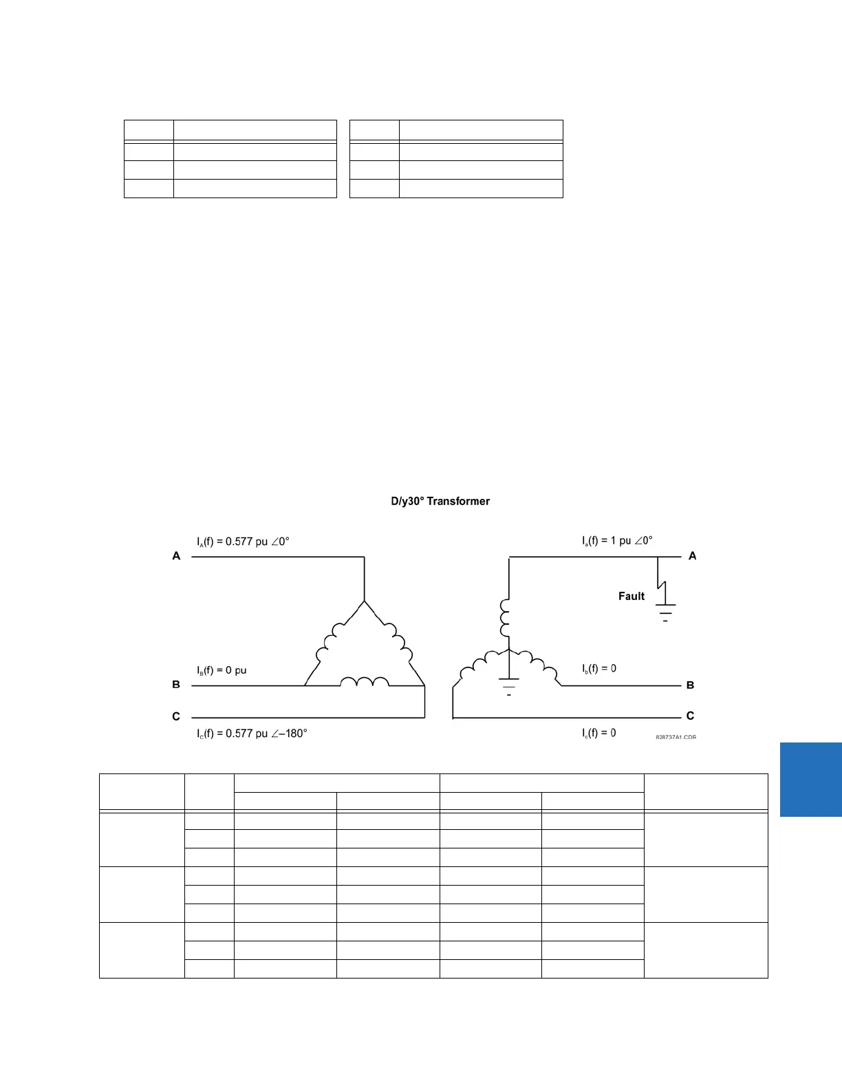
8.2.3.1 D/yg30° transformer with phase A to ground fault on the grounded Wye
Transformer data — D/y30°, 20 MVA, 115/12.47 kv, CT1 (200:1), CT2 (1000:1)
Figure 8-3: Current distribution of a D/yg30° transformer with an LV-side ground fault
Phase Differential current (I
d
) Phase Restraint current (I
r
)
A0 ∠0° A 0 ∠0°
B 8.631 pu ∠–180° B 9 pu ∠–180°
C 8.631 pu ∠0° C 9 pu ∠0°
Test Phase Injected current Displayed current Status
W1 current W2 current Differential Restraint
Balanced
Condition
A 0.29 ∠0° 0.926 ∠–180° 0 ∠0° 0.5349 ∠–180° Not Applicable
B0 ∠0° 0 ∠0° 0 ∠0° 0 ∠0°
C 0.29 ∠–180° 0 ∠0° 0 ∠0° 0.5349 ∠0°
Minimum
Pickup
A 0.137 ∠0° 0.521 ∠–180° 0.048 ∠0° 0.3 ∠–180° Block
I
d
= 0.048 < Min PKP
B0 ∠0° 0 ∠0° 0 ∠0° 0 ∠0°
C 0.137 ∠–180° 0 ∠0° 0.048 ∠0° 0.3 ∠0°
Minimum
Pickup
A 0.108 ∠0° 0.521 ∠–180° 0.102 ∠0° 0.3 ∠–180° Operate
I
d
= 0.102 > Min PKP
B0 ∠0° 0 ∠0° 0 ∠0° 0 ∠0°
C 0.108 ∠–180° 0 ∠0° 0.102 ∠0° 0.3 ∠0°
 Loading...


