GE HEALTHCARERAFT VOLUSON E8 / VOLUSON E6
D
IRECTION KTD102576, REVISION 7 DRAFT (AUGUST 23, 2012) SERVICE MANUAL
8-26 Section 8-17 - Replacing optional Peripherals / How to mount Peripherals at a later date
8-17-3 Mounting/Replacing the VGA Image (Video) Resizer
NOTE: Mounting/Replacement procedure depends on the connector plate (on back of the console).
• for systems with a power connector for auxiliary devices, see Section 8-17-3-1 on page 8-26
• for systems without a power outlet for auxiliary devices, see Section 8-17-3-2 on page 8-28
8-17-3-1 Installation Procedure at systems WITH power connector
1.) Power Off/Shutdown the system as described in Section 4-3-2 on page 4-4.
2.) Peel off the protective film from the adhesive tapes (on Power Supply) and fix the Power Supply
onto the Image Resizer Box.
3.) Peel off the protective film from the adhesive tapes (on bottom of Image Resizer Box) and fix the
complete package on the shelf at the rear side of the system (see: Figure 8-28 below).
!! NOTICE:
The VGA Image (Video) Resizer is required whenever the used Secondary “Patient” Monitor has a
different screen resolution than the Voluson E8 / Voluson E6 system!
!! CAUTION:
A Secondary “Patient” Monitor MUST NEVER be connected to the Voluson E8 / Voluson E6
ultrasound systems mains supply directly!
Always connect it to an appropriate Isolation Transformer (see: Table 9-17 on page 9-34)!
!! WARNING:
After each installation, the leakage currents have to be measured according to
IEC 60601-1 respectively UL 60601-1.
!! NOTICE:
The VGA Image (Video) Resizer is required whenever the used Secondary “Patient” Monitor has a
different screen resolution than the Voluson E8 / Voluson E6 system!
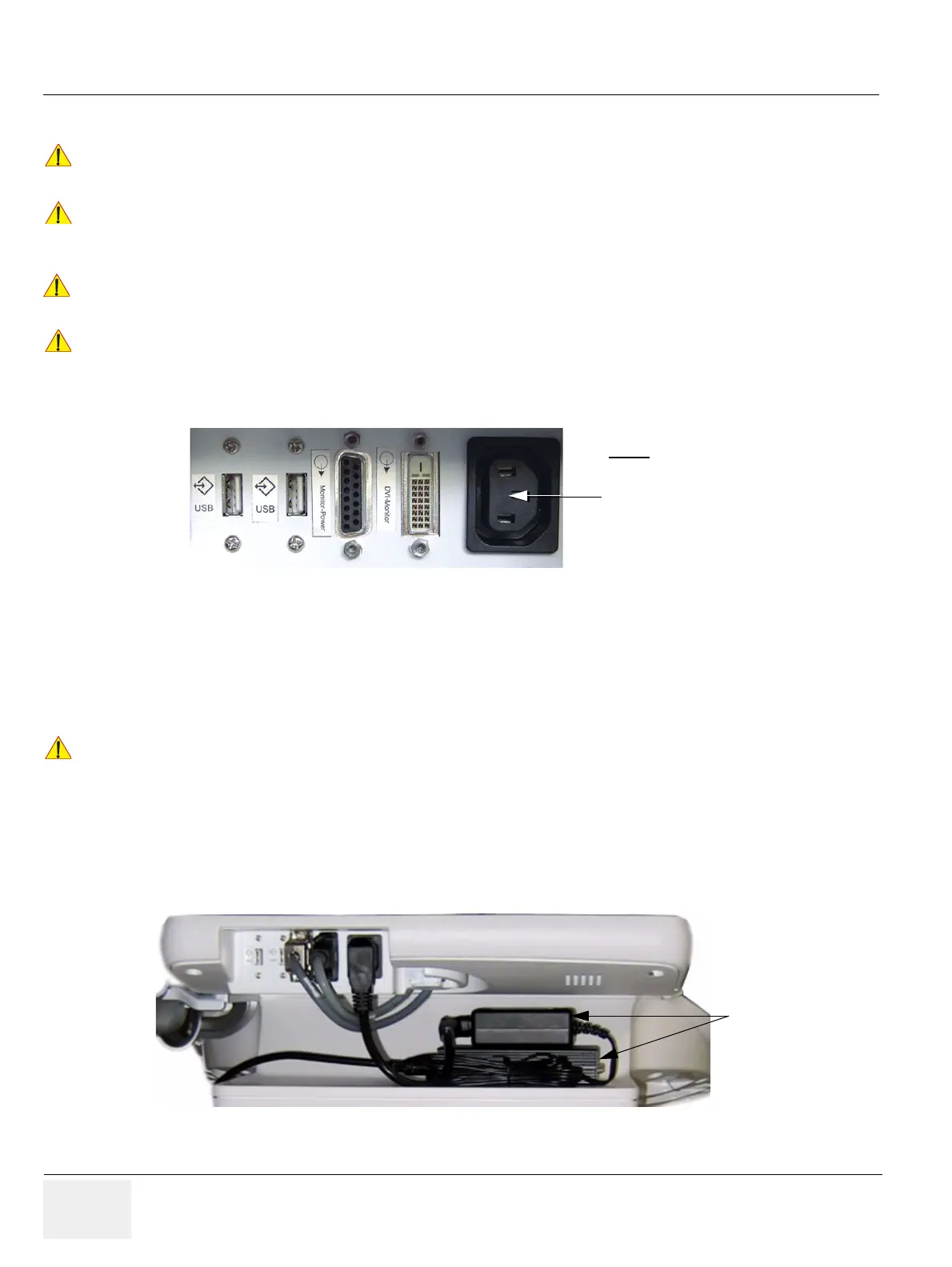
Figure 8-27 connector plate on back of the console
!! NOTICE:
Following steps describe, how to install the VGA Image Resizer (if it was not mounted before).
Figure 8-28 Power Supply and Image Resizer on shelf at rear side of the system
Note:
The main outlet for auxiliary devices is
not available at systems with BT10/
BT12/BT13 hardware version
(or, if the main harness has been replaced).
Power Supply &
Image Resizer Box
on shelf at rear
side of the system

 Loading...


