4 - Sprayer setup
40
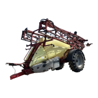
Power supply
Power requirement is 12V DC. Always note polarity! For proper function
of the electric equipment, the wires must have the following
recommended cross sectional areas and correct fuses to ensure a
sufficient power supply. The delivered power connectors follows the
standard of most newer tractors. If you have a tractor with another
power connector, it is necessary to disassemble the connector and fit it
to the actual tractor connector.
The number and type of connectors may vary on the specific sprayer,
depending on its equipment.
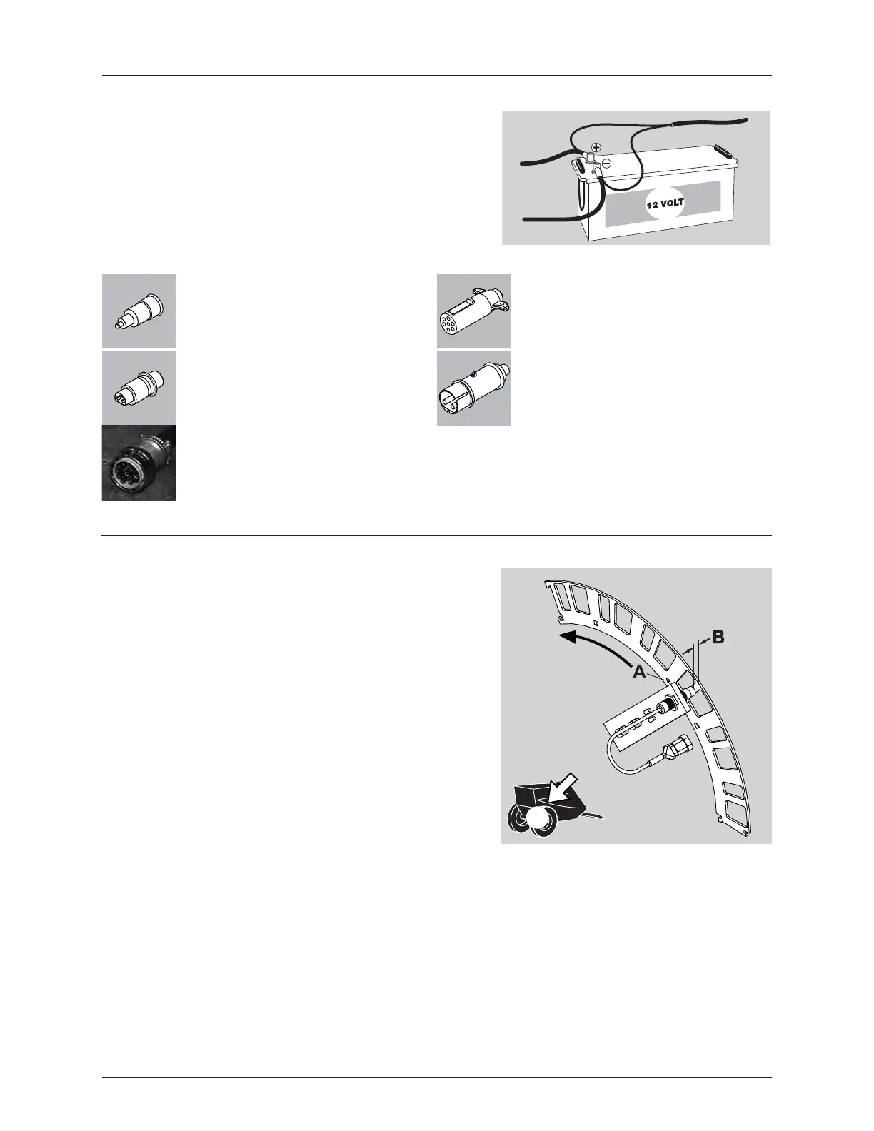
Speed transducer for sprayer
The speed transducer and speed ring are located at the inside of the
sprayers right wheel. The sensor is an inductive type that requires a
metallic protrusion like a speed ring to pass by it to trigger a signal.
Adjustment
1. Assure that the speed ring is correctly fitted to the wheel, so that
the arrow (A) follows the forward rotation of the wheel.
2. Adjust so the sensor lines up in the middle of the gaps in vertical
direction.
ATTENTION! If necessary readjust plate on the axle.
3. Adjust air gap (B) to 1/8” (3.0 mm). Use feeler gauge or similar tool.
4. After adjustment, rotate the wheel. Verify air gap variation of less
than +/-0.02” (+/-0.5 mm). Check this for the entire circumference.
÷
NOTE! Air gap variation adjustment is made using the carriage bolts for the speed ring.
5. Verify Speed at the controller.
ATTENTION! Correct fitting is indicated by continuous flashing from transducer when the wheel rotates.
CIGAR CONNECTOR
Spray control unit requires:
Wire 2.5mm², Fuse 10 Amp
Hydraulic control unit requires:
Wire 10 awg. (4.0 mm²), Fuse 16 Amp
7 POLE TRAFFIC LIGHT CONNECTOR
JOBCOM CONNECTOR
The unit requires:
Wire 6.0 mm², Fuse 25 Amp
WORKING LIGHT CONNECTOR
The unit requires:
Wire 10.0 mm², Fuse 30 Amp
ISO POWER CONNECTOR
 Loading...