4 - Sprayer setup
44
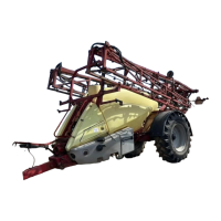
Dual tire setup - Pre 2014 (optional)
Two different dual tire kits are available for the COMMANDER:
22” row spacing (88”/132”): HARDI® ref. no. 70059503
30” row spacing (60”/120”): HARDI® ref. no. 70059603
1. Attach the sprayer to tractor and engage tractor parking brake.
2. Place stop wedges in front of, and behind RH wheel. Jack up LH
wheel, support and secure sprayer body.
3. Remove LH tire and set aside. Install supplied LH tire (chamfered
holes) and secure with supplied inner bud wheel nuts. Tire offset
must be as shown in order to maintain 22” or 30” spacing between
center of inside tire to center of outside tire.
4. Attach dual spacer and secure with supplied outer bud wheel nuts
(flat side towards rim).
5. Attach outer LH tire (removed in step 3) to dual spacer with
supplied wheel studs and wheel nuts removed in step 3. Make sure
the distance between the center of inside tire to center of outside tire is 22” or 30”. Wheels may need to be reversed
and exchanged.
6. See “50 hours service - Wheel nuts” on page 67 for proper torque and tightening sequence.
7. Repeat the procedure for RH wheels.
8. Re-tighten bolts and wheel bolts to specified torque after 8 hours of work.
9. Check the distance between the center of inside LH tire to center of inside RH tire. The distance must be 88” for 22”
duals, or 60” for 30” duals. If necessary, adjust the track width. See “Altering the track width (adjustable axle)” on page 42.
±
WARNING! Securely support the sprayer during axle adjustments. Never attempt to adjust axles with liquid in the tank.
Always block wheels on opposite side when adjusting axles.
ATTENTION! The wheels supplied with the dual tire kits must be used on the inside tires only. The rims have
chamfered holes to match the supplied inner bud wheel nuts.
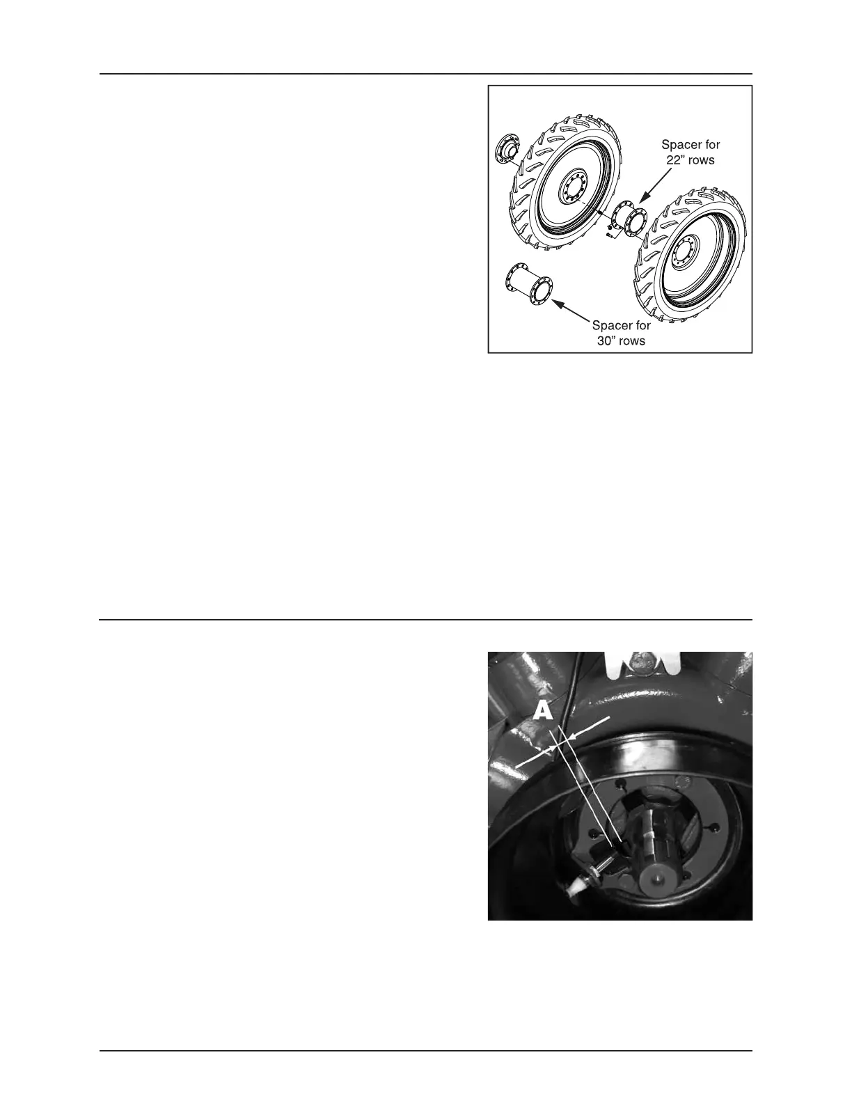
R.P.M. Transducer for pump
The R.P.M. transducer is located at the inner side of the P.T.O. shield. The
sensor is an inductive type that requires metallic protrusions to pass by
it to trigger a signal.
Adjustment
1. Adjust air gap (A) to 3/16” (4 mm). Use a feeler gauge or similar tool.
2. After adjustment, spin the shaft. Verify air gap variation of less than
+/-0.02” (+/-0.5 mm). Check this for the entire circumference.
3. Verify transducer function:
• ISOBUS VT:
Monitor menu [4.5.4.9.6 PTO pump frequency].
 Loading...