2. The water sensor should be installed on the pool loop prior to the heater(s) and will display the
pool temperature whenever the “Pool Filter” pump is running.
3. The dual equipment spa sensor should be installed on the spa loop prior to the heater(s) and
will display the spa temperature whenever the “Spa Filter” pump is running.
4. The OmniPL can be programmed to accommodate spillover if desired. Note that spillover
operation will be automatically suspended whenever the spa filter pump is turned on.
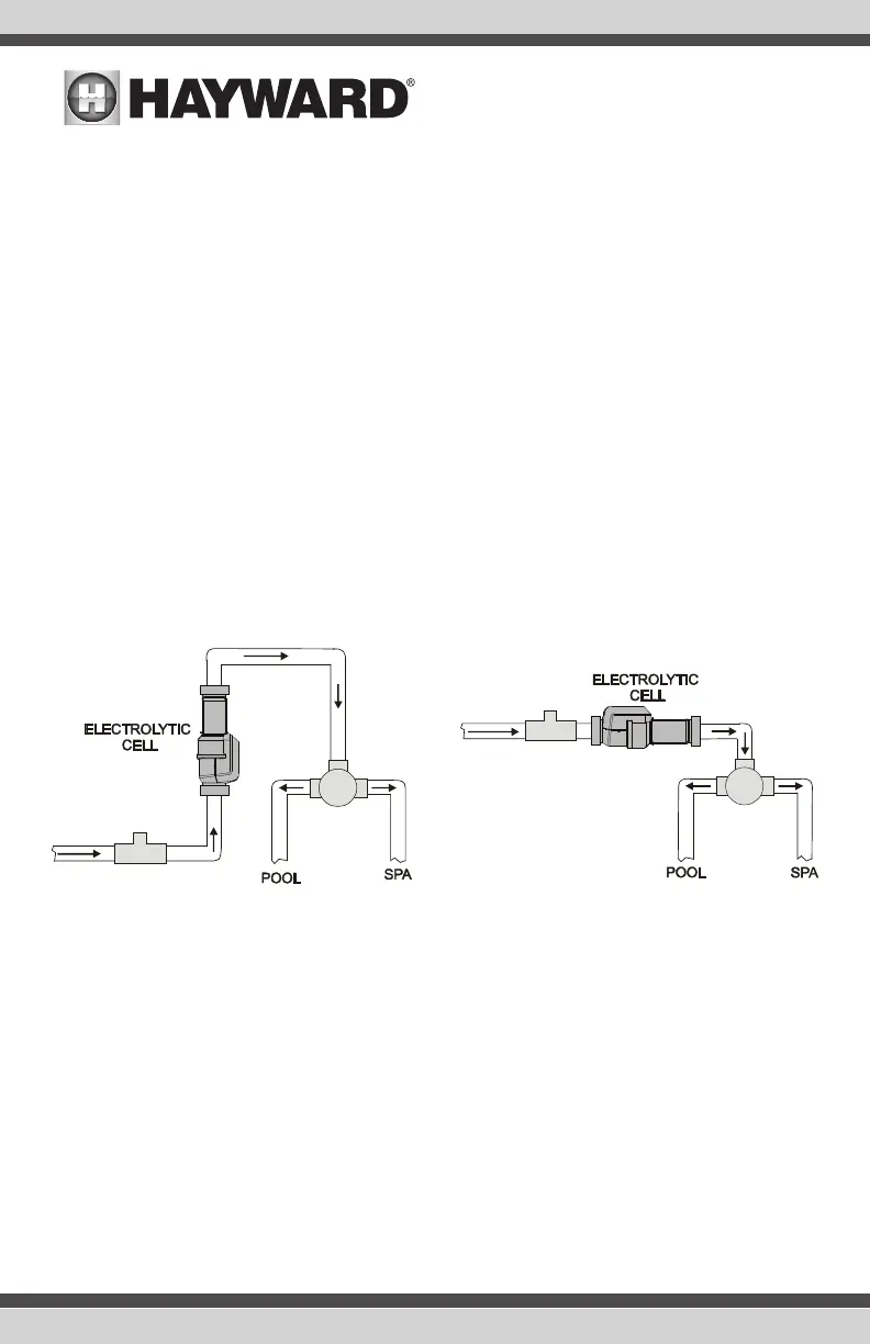
5. The chlorinator cell and flow switch must be installed in the heater return path. If spillover is
enabled, then the OmniPL can chlorinate both the pool and spa (during spillover operation). If
not using spillover, the OmniPL can control an AquaRite (purchased separately) for chlorination
of both bodies of water.
6. If any water feature or pressure side cleaner boost pumps are used, be sure to enable the “in-
terlock” feature (see CONFIGURATION for details) to ensure that the pumps operate only when
the “Pool Filter” pump is on.
7. The plumbing diagram above is intended to be used as a general guideline and is not a com-
plete plumbing schematic for the pool.
TurboCell (HLPRO4NSW only)
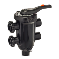
The TurboCell must be plumbed AFTER the filter and heater. If installed on a pool/spa combination
system, the cell must be plumbed BEFORE the pool/spa return valve in order to allow proper chlori-
nation of both the pool and the spa. Refer to the plumbing diagram below:
The cell may be mounted vertically or horizontally, and water can move in either direction through the
cell. Install using the 2” unions provided. Tighten unions BY HAND for a watertight seal. For systems
with 1½” plumbing use adapters (provided by installer).
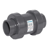
Flow Switch
A Hayward GLX-FLO flow switch is required if chlorination or an HL-CHEM ORP & pH Sensing Kit
will be used. If no chemistry equipment is installed, the GLX-FLO is optional and can be used to
detect leaks or clogs in your pool’s plumbing system. If using the GLX-FLO, it must be plumbed in
line with any chemistry sensing/dispensing equipment at the very end of the return plumbing. This
will ensure that the OmniPL will detect a leak if it occurs anywhere at the pool pad. Understand that
if a leak occurs after the flow switch (downstream), the OmniPL will not sense a "no-flow" condition.
IMPORTANT: There must be at least a 12” (30cm) straight pipe run before (upstream) the flow switch.
IMPORTANT: To ensure proper operation, verify that the arrow on the flow switch points in the direc-
tion of water flow.
13
USE ONLY HAYWARD GENUINE REPLACEMENT PARTS
 Loading...