Overview
Before attempting to install the OmniPL, familiarize yourself with the installation steps on the follow-
ing pages. Also refer to the sample overview diagram on page 6. In this example, the high voltage
to the OmniPL wiring panel, variable speed pump (VSP), heater, and Smart Relay come directly from
circuit breakers in the main service panel. Low voltage communication from the OmniPL turns these
devices on and off. If there were a single speed pump in the system, the power would come from
a breaker at the main panel through one of the OmniPL’s internal relays or a Smart Relay. In that
scenario, the relay would turn the pump on and off.
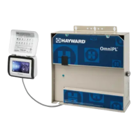
The OmniPL offers connectivity to the web through the home’s network. Once connected, web en-
abled devices such as a PC, laptop, tablet or phone can be used to control and monitor the OmniPL.
The overview diagram on page 6 is offered as a guide and it’s likely that your installation will differ.
Refer to the following pages for specific wiring information. Be aware of each circuit breaker’s rating
and don’t exceed their rated load.
Installation Steps
DANGER of Death, Injury or Property Damage if procedure not followed. Dead front panel
removal is required for this installation. Power to the OmniPL wiring panel MUST be shut off before
the dead front is removed.
Details on each installation step are presented on the following pages:
1. Mounting the equipment (page 7)
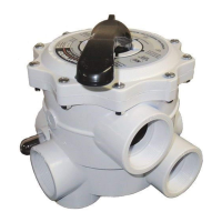
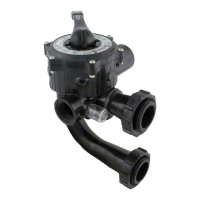
2. Plumbing (page 10)
3. Electrical Wiring (page 14)
4. Prepare the pool water (page 26)
5. System Startup, Firmware Upgrade and Configuration (page 29)
NOTE: If replacing a Pro Logic Controller using networked ColorLogic Lights, the lights must be put
into “Standalone” (default) mode before disconnecting the Pro Logic. The OmniPL can only control
ColorLogic lights in “Standalone” mode.
5
USE ONLY HAYWARD GENUINE REPLACEMENT PARTS
 Loading...