230 VAC
Connection Table
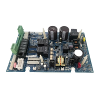
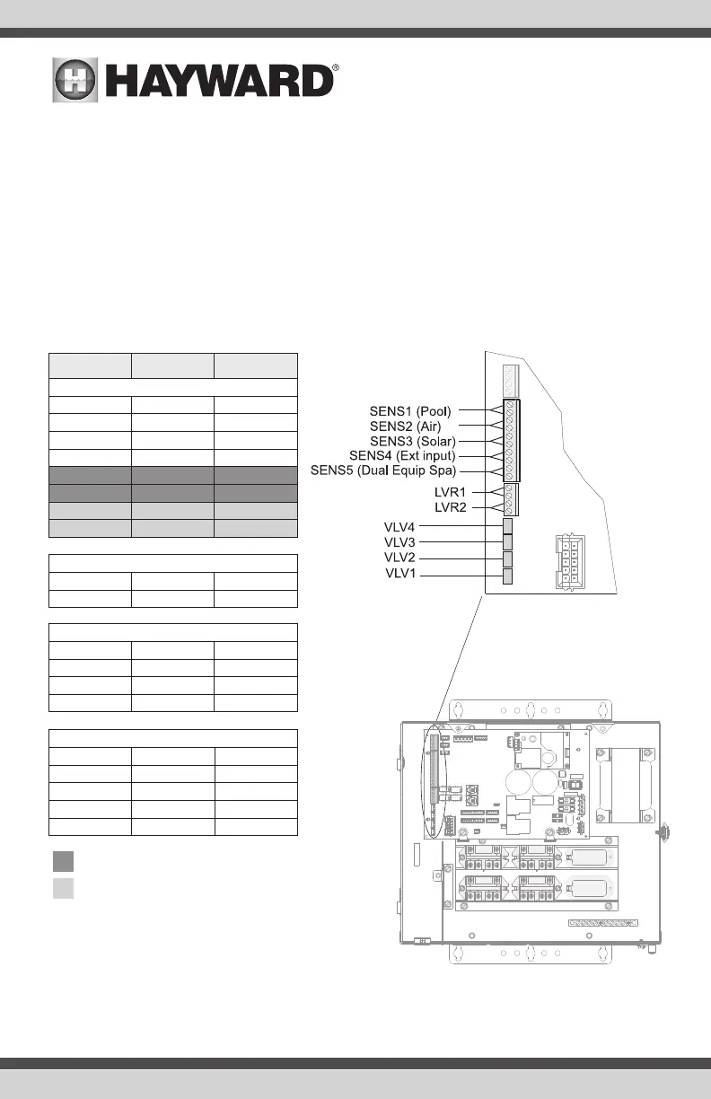
The OmniPL includes 4 high voltage relays (HVR1-HVR4), 2 low voltage/heater relays (LVR1-LVR2),
4 valve outputs (VLV1-VLV4) and 4 temperature sensors/1 external input sensor (SENS1-SENS5).
Two additional HLRELAYS (HVR9 and HVR10) as well as two additional Smart Relays (HVR1) can be
added. When wiring pool equipment to the OmniPL, keep a record of all connections. You’ll need to
record which input/output is used and what equipment is attached. To aid in this process, use the
table below. To identify the various inputs/outputs, refer to the diagram on the side of the table. After
attaching equipment to the OmniPL, fill in the appropriate information in the table.
Connection Table
Low Voltage Relays/Heaters
Valve Acutators
Temperature Sensors
Connection
HVR1
LVR1
SENS1 POOL
SENS5 DE SPA
VLV1
HVR2
HVR1 Smart Relay
LVR2
SENS2 AIR
VLV2
HVR3
HVR9
HVR10
SENS3 SOLAR
VLV3
HVR4
HVR1 Smart Relay
SENSE4 EXT INP
VLV4
Pool Equipment
Description
High Voltage Relays
Optional Smart Relays
Optional Internal High Voltage Relays
HVR9
HVR10
HVR1
HVR2
HVR3
HVR4
USE ONLY HAYWARD GENUINE REPLACEMENT PARTS
16
 Loading...