2.2 - PCB
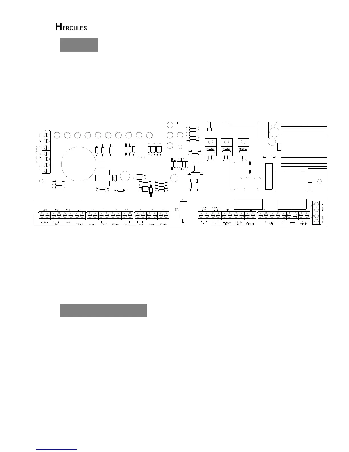
There are three fuses mounted on the circuit board. All are 20mm anti-surge
F1 1.6A – to protect the positive (+Ve) line of 12V battery
F2 1A – to protect the RKP 13V supply
F3 1A – to protect the Siren (Bell)&Strobe supply
As supplied, wire links are fitted across the Tamper terminal to represent a closed circuit.
CAUTION: Always power-down the panel when wiring external circuits, to prevent
damage to the panel electronics.
Systematically wire and test each circuit:
• Zone, Tamper circuit and PA circuits
• Finish by wiring any additional extension speaker, sounders, external siren (bell)/strobe and
the 13V supply.
2.3 - Tamper network
The Tamper circuit is used to protect all cables and detectors in the system from unauthorized
access including the panel and RKP covers.
The zone and PA tampers should be series wired and connected to the terminals.
Terminals RTN-&- are for the external siren tamper. The TAMP terminals at the bottom left of
the board are for the RKP tampers.

 Loading...