5. Servo operating
4-9
FDA7001 ~ 02 type does not have control circuit power r, t terminals.
(Note3) The regenerative resistor of FDA7004 ~ FDA7010 is built-in and is mounted inside
the drive. The regenerative resistance of FDA7001, 7002, 7004B and FDA7015 ~
7750 models is a separate type. Please apply after confirming the capacity.
Please contact our sales team for regenerative resistance of models FDA7075 ~
7750.
(Note4) Be sure to ground the ground wire of CN1 cable to FG (Frame Ground) terminal.
(Note5) Apply position command pulse when outputting by line drive method.
(Note6) Apply position command pulse when outputting by open collector method.
(Note7) Apply the Z phase pulse when outputting by line drive method.
(Note8) Apply the Z phase pulse when outputting by open collector method.
(Note9) Be sure to connect GND24 (CN1-24, 25) and GND (CN1-1, 8, 26, 33, 34, 36)
separately.
In case of common connection, malfunction or damage of servo drive may occur.
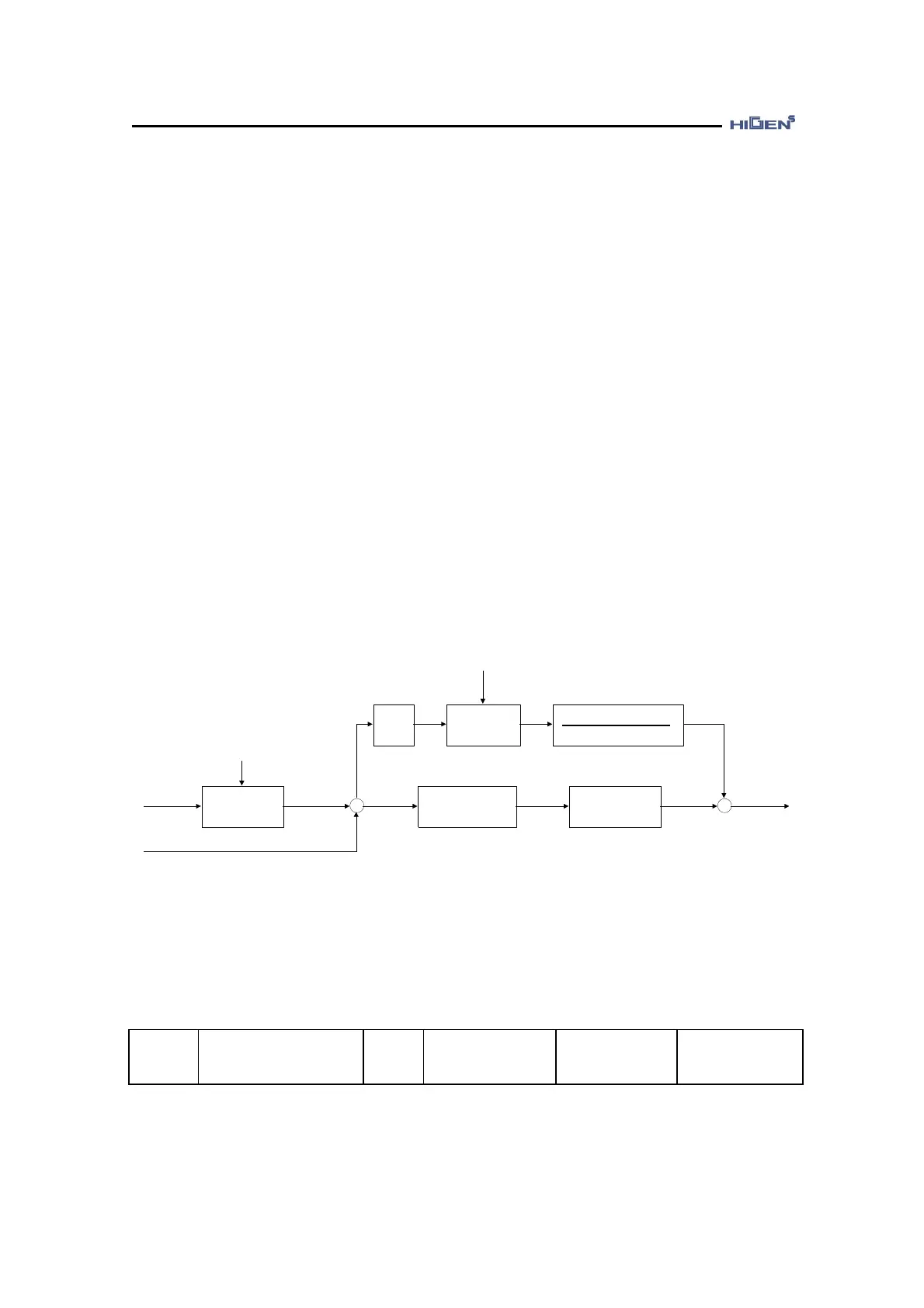
4.2.2. Position servo gain adjustment
Position
command
1st filter
[Position command pulse TC
(P05-10)]
+
-
Internal
position
command
Position
Differentiation
1st filter
[Feed forward TC (P05-11)]
[PC P Gain
(P05-05, P05-06)]
+
+Position
error
Speed
command
[Feedforward (P05-04)]
100
[POS Gain mode
(P05-01)]
(Note) In this control mode, Error pulse should be cleared according to the servo condition.
Before the stop function release, the error pulse is cleared by PLSCLR action.
1) This sets the position control gain mode.
When the servo drive set to position control mode, this sets the position control gain mode.
 Loading...