5. Servo operating
4.2. Gain adjustment method for position control mode
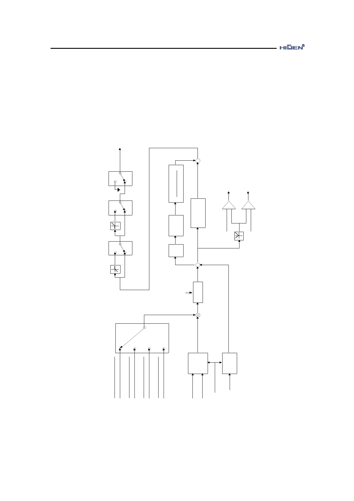
Pulse type selection
[Pulse type (P05-02)]
( ) : Contact point input
[ ] : Set value
Pulse
counter
(PPFIN)(PFIN)
(PPRIN)(PRIN)
Position
counter
Encoder
(CLR)
Clear when ON
Electronic gear
(GEAR1,GEAR2)
(OFF,OFF)
(ON,OFF)
(ON,ON)
(OFF,ON)
1st
filter
[Command pulse TC
(P05-10)]
+
-
Internal
position
command
Position
Differentiation
1st
filter
[Feed forward TC
(P05-11)]
PC P gain
(P05-05, P05-06)
+
+
Position
error
+
-
+
-
[In position (P05-08)]
[Follow error pulse (P05-09)]
In position completed
(in case of + > -)
Following error
(in case of + > -)
CCW revolution limit
(CCWLIM)
(OFF)
(ON)
CW revolution limit
(CWLIM)
(OFF)
(ON)
Emergency stop
(ESTOP)
(OFF)
(ON)
GND
Internal
speed command
[Feed forward (P05-04)]
100
[ELCTR Gear1 NUM (P05-12)]
F pulse
[ELCRT Gear1 DEN (P05-13)]
[ELCRT Gear2 NUM (P05-14)]
[ELCRT Gear2 DEN (P05-15)]
R pulse
[ELCTR Gear3 NUM (P05-16)]
[ELCTR Gear4 NUM (P05-18)]
[ELCRT Gear3 DEN (P05-17)]
[ELCRT Gear4 DEN (P05-19)]
 Loading...