2. Wiring and connection
2-15
2.4. Power handling
2.4.1. Wiring
If you turn the power on and off frequently, the peripheral elements of the main circuit will
deteriorate because a large charging current (charging time 0.3 to 0.5 seconds) flows when the
main power is turned on. Therefore, be sure to use STOP contact for motor operation and stop,
and SVONEN contact for emergency stop.
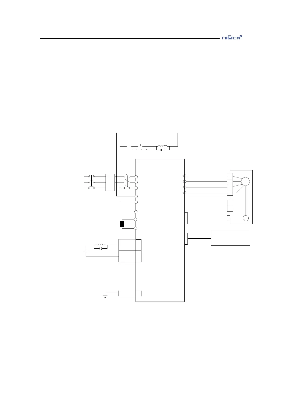
The figure below is an example of wiring of power
Servo Drive
FDA7000
R
S
T
r
t
P
B
CN1
(INPUT)
+
-
24V
U
V
W
FG
SM
+
-
Brake Power
Input
U
V
W
FG
PG
ENC(CN2)
COM(CN3)
NF
FDA7000 Series : AC 200~230V
FDA7000-H Series : AC 380~440V
50/60Hz
NFB MC1
Regenerative
resistance
*PC Loader(RS232C)
*Network communication
(RS485, RS232C)
(Note1)
(Note2)
FG
50
(Note4)
(Note3)
ALARM
20
GND24
24
25
1Ry
Diode
1MC
Surge killer
1Ry1MC
POWER
ON
POWER
OFF
N
(Note1) A noise filter (NF) must be installed to block noise from the outside and to protect the
servo drive peripherals.
(Note2) In case of FDA7001~7002, it is not necessary to connect power to the power terminals
"r, t" of the control circuit.
In case of FDA7004~7150, connect AC220V to power terminal “r, t” of control circuit.
 Loading...