2. Wiring and connection
2-22
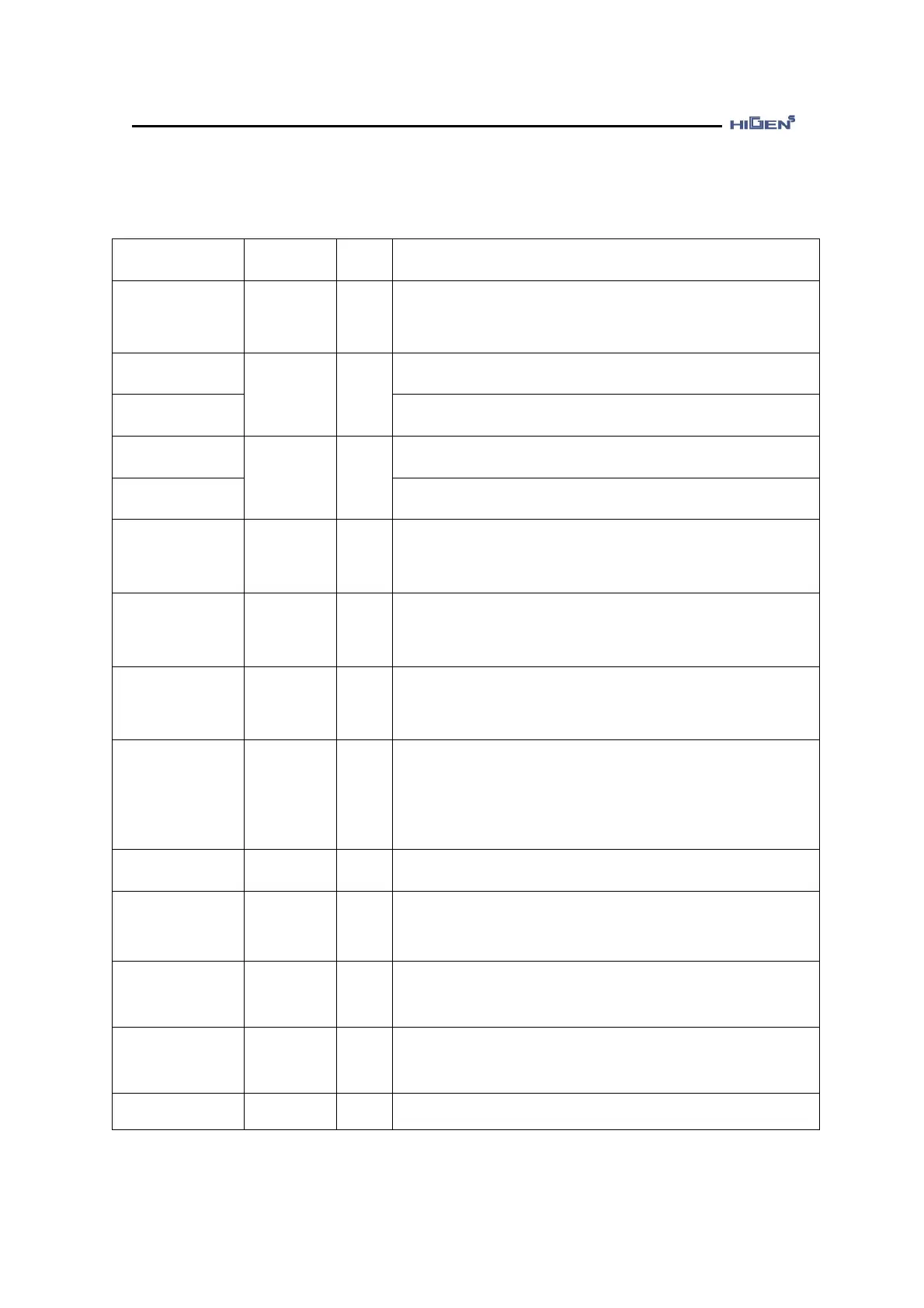
2.5.5. Fixed I/O signal function table
Function and usage explanation
F+ input pulse
F- input pulse
R+ input pulse
R- input pulse
Depending on the set value of pulse logic, it receives and
operates according to the specific position command type
of negative or positive logic. Refer to Chapter 3 for details
of the pulse type.
When operating in speed mode, enter the analog speed
command.
When operating in torque mode, enter the analog speed
limit.
When operating in torque mode, enter the analog torque
command.
When operating in speed mode, enter the torque limit.
Designated variable value is outputted in 0~5[V] range
through the DA converter.
[Monitor selection] 0: Speed, 1: Speed command, 2: Torque,
3: Torque command, 4: Pulse, 5: Command pulse
Designated variable value is outputted in 0~5[V] range
through the DA converter.
[Monitor selection] 0: Speed, 1: Speed command, 2: Torque,
3: Torque command, 4: Pulse, 5: Command pulse
PAO,/PAO
PBO,/PBO
PZO,/PZO
After dividing the motor encoder signal from CN2 as much
as the division rate set in the division setting menu, it
outputs in line drive method.
As the external I/O contact point power, enter
+24[VDC]10% 1.0[A] or above for the external power.
(User preparation)
When using the I/O contact point power simultaneously,
recalculate the power capacity according to the output
contact points.
Connect the ground of power+24[VDC]10% for external
I/O contact point. (User preparation)
Common power ground terminal of speed, command,
torque limit command, speed, torque monitor output,
encoder output terminal.
When using the absolute encoder, connect the battery from
the host controller. Do not connect the drive side and both
sides of the host controller.
+12[V] output
-12[V] output
When simply outputting speed command and torque limit,
use the 12[V] power.
Ground the cable ground wire of CN1.
♥ Function of fixed I/O contact point cannot be changed.
 Loading...